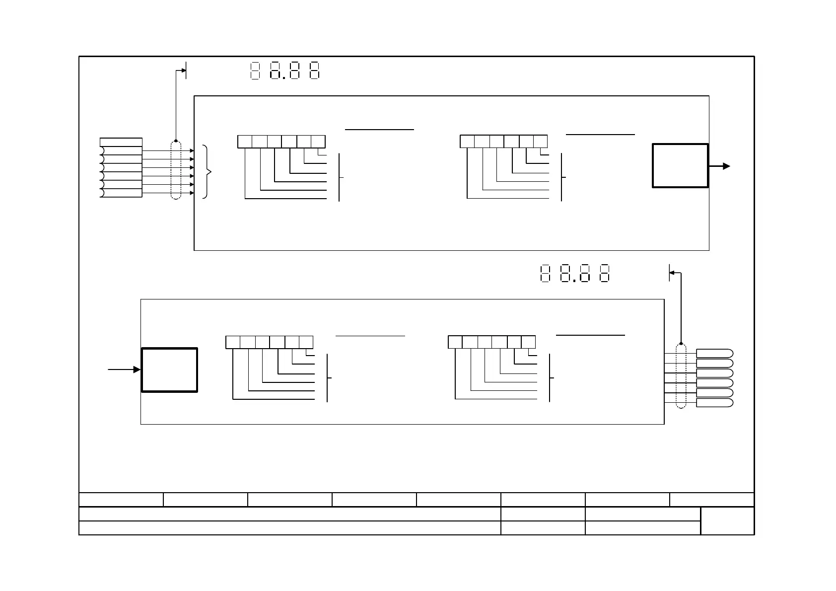
Function diagram
87654321
fp_mc_813_e.vsd
Technology option
MASTERDRIVES MC
24.10.01
Digital inputs / outputs for positioning
-813 -
<1> Example of configuring the digital inputs for positioning:
MD45=7xxxxx) ==> Digital input, terminal X101.8 [90] =
Reference-point proximity switch U536.06 = 20)
<2> Example of assigning the digital outputs for positioning:
MD47 = xxx4xx ==> Binector B313 = "M change from M97"
<3> Double assignment of an input or output with more than one function is not premitted.
Factory setting digital
inputs at X101 [90]:
E4 = B016 = Terminal 6
E5 = B018 = Terminal 7
E6 = B020 = Terminal 8
E1
E2
E3
E4
E5
E6
Selection of function 1
0 = No function
1 = Start OR operation
2 = Start AND operation
3 = Position-feedback setting
on-the-fly (for automatic mode)
4 = External block change
(for automatic mode)
5 = In-process measurement
6 = Collision (for automatic mode)
7 = Proximity switch for reference
point [821.4]
8 = Reversing cam for
homing [821]
9 = Read-in enable, external, dependent
on program (for automatic mode)
MD45 10
5
10
4
10
3
10
2
10
1
10
0
E1
E2
E3
E4
E5
E6
MD46 10
5
10
4
10
3
10
2
10
1
10
0
E1
E2
E3
E4
E5
E6
Digital inputs E1 ... E6 for positioning
Function is specified by means of MD45 and MD46 <1> <3>
Selection of function 2
<5>
0 = No function
1 = Disable actual value
2 = External
Read-in enable
3 = External read-in enable
AND operation
4 = Reference point setting
on the fly <4>
5-7 = No function
8 = Trigger signal engage/
disengage OR'd
9 = Synchronize travel table OR'd
to the operating modes
Digital
inputs
for positioning
Selection of function 1
0 = No function
1 = Position reached an
stop [DRS]
2 = Axis moves forwards [FWD]
3 = Axis moves backwards [BWD]
4 = M change from M97
(for automatic mode)
5 = M change from M98
(for automatic mode)
6 = Start enable [ST_EN]
MD47 10
5
10
4
10
3
10
2
10
1
10
0
A1
A2
A3
A4
A5
A6
MD48 10
5
10
4
10
3
10
2
10
1
10
0
A1
A2
A3
A4
A5
A6
Digital outputs A1 ... A6 for positioning
Function is specified by means of MD47 and MD48 <2> <3>
Selection of function 2
<6>
0 = No function
1 = Constant travel
2 = Acceleration phase
3 = Deceleration phase
4 = Acceleration or
deceleration phase
5 = Pre-position reached
(see also MD34 and MD35)
6 = Encoder monitoring
signal
from the operating modes
Digital
outputs
for positioning
A1
A2
A3
A4
A5
A6
2
1
2
2
2
4
2
0
2
3
2
5
2
1
2
0
2
3
2
2
2
5
2
4
Display on PMU
2
1
2
0
2
3
2
2
2
5
2
4
Display on PMU:
V2.5
<4> The measured position value memory is used for this function, and one of the
digital inputs, terminal 6 or 7, must be used [90.3].
<5> Function 1 - 3 for roller feed only
<6> For roller feed only
B
U536
.01 (0) 2
0
B
.02 (0) 2
1
B
.03 (0) 2
2
B
.04 (16) 2
3
B
.05 (18) 2
4
B
.06 (20) 2
5
B0311
B0312
B0313
B0314
B0315
B0316
n542.01
n542.02
 Loading...


