Communication / CBC CANopen Communication Board 02.2004
6SE7087-6QX70 (Version AD) Siemens AG
8.5-120 Compendium Motion Control SIMOVERT MASTERDRIVES
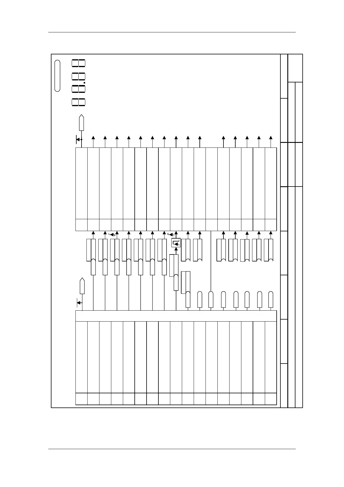
Interconnection diagram
87654321
CANopen contr.word to MASTERDRIVES control word 1
MASTERDRIVES MC
- 8513 -
to seq. control 1)
to seq. control 1)
to seq. control 1)
to seq. control 1)
to seq. control 1)
to setpoint processing (Part 2) [320.3]
to setpoint processing (Part 1) [310.7]
to seq. control 1)
to seq. control 1)
to seq. control 1)
to setpoint processing (Part 1) [310.7]
to motor potentiometer
[300.2]
to seq. control 1)
to fault processing
Note: This bit must be set in the first PZD word of the
message received from the serial interface to ensure that
the converter accepts the process data as valid (cf. USS,
Profibus, etc.; does not apply for SIMOLINK)
to setpoint pocessing (Part 2) [320.2]
The sequential control
is the internal control
(software) that
implements the
converter state (r001).
1)
BICO parameter
default settings:
1st binector applies to
BICO data set 1
n959.25 = 4
15 14
76
13 12
54
11 10
32
98
10
Display of r550 on PMU
P555.B (1/20)
B
Src1OFF2(electr)
P558.B (1/1)
B
Src1OFF3(QStop)
P554.B (0/0)
B
SrcON/OFF1
P561.B (1/1)
B
Src InvRelease
P562.B (1/1)
B
SrcRampGen Rel
P563.B (1/1)
B
Src RampGenStop
P564.B (1/1)
B
SrcSetpRel
P568.B (0/0)
B
P569.B (0/0)
B
P571.B (1/1)
B
P572.B (1/1)
B
P574.B (0/0)
B
P575.B (1/1)
B
P573.B (0/0)
B
P565.B(2107)
B
Src1 Fault Reset
0=OFF1 stop via RFG, then
pulse disable
1=ON, oper. condition (edge-triggered)
Meaning
0=OFF2
,pulse disable, motor coasts to standstill,
1=operating cond.
0=OFF3, quick stop
1=Operating cond.
1=Enable inverter, pulse enable
0=Pulse disable
1=Enable RFG
0=Set RFG to 0
1=RFG start
0=RFG stop
1=Enable setpoint
0=Disable setpoint
0 ⇒ 1 edge acknowledge error
1=Inch bit 0
1=Inch bit 1
1=Control requested ,
0=No control requested
1=Enable positive rot. direction,
0=pos rot. direction disabled
1=Enable neg. rot. direction
0=neg. rotational direction disabled
1=Raise MOP
0=External fault 1 (F035)
1=no external fault
1=Lower MOP
Bit 1
Bit 2
Bit 3
Bit 4
Bit 5
Bit 6
Bit 7
Bit 8
Bit 9
Bit 10
Bit 11
Bit 12
Bit 13
Bit 14
Bit 15
Bit
No.
Bit 0
1=Switch on, bit acts directly on OFF1
0=Switch off, OFF 1 is activated
Meaning
1=Enable Voltage, bit acts directly on OFF2
0=Disable Voltage, motor is de-
energized
1=No Quick stop, bit acts directly on OFF3
0=Quick stop, drive is de-
celerated along current limit
1=Enable Operation, bit acts directly on
inverter enable
0=Disable Operation
Mode specific
Mode specific
Mode specific
1=Reset Fault
bit acts directly on Acknowledge
Error (acknowledgement by edge change only
0=No Reset Fault
1=Halt, acts in different modes on different bits
0=No stop
Reserved
Reserved
Mode specific
1=one is connected through,
0=zero is connected through
1=one is connected through,
0=zero is connected through
1=one is connected through,
0=zero is connected through
Bit 1
Bit 2
Bit 3
Bit 4
Bit 5
Bit 6
Bit 7
Bit 8
Bit 9
Bit 10
Bit 11
Bit 12
Bit 13
Bit 14
Bit 15
Bit
No.
Bit 0
Interconnections of CANopen software on the CBC
B3100
B3101
B3102
B3103
B3104
B3105
B3106
B3107
B3108
G90/G91
U078.B (0)
B
BIN/CON Conv 3
B3109 reserved
B3110
reserved(always 1)
B3111 reserved
B3112 reserved
B3113 freely connect.
B3114 freely connect.
B3115 freely connect.
Control word 1
r550
K0030
Control word 1
CB data word 1
r733.01
K3001
Mode specific
MASTERDRIVES MC F01
from V1.5
01.10.01
to motor potentiometer
[300.2]
2nd binector applies to
BICO data set 2
 Loading...


