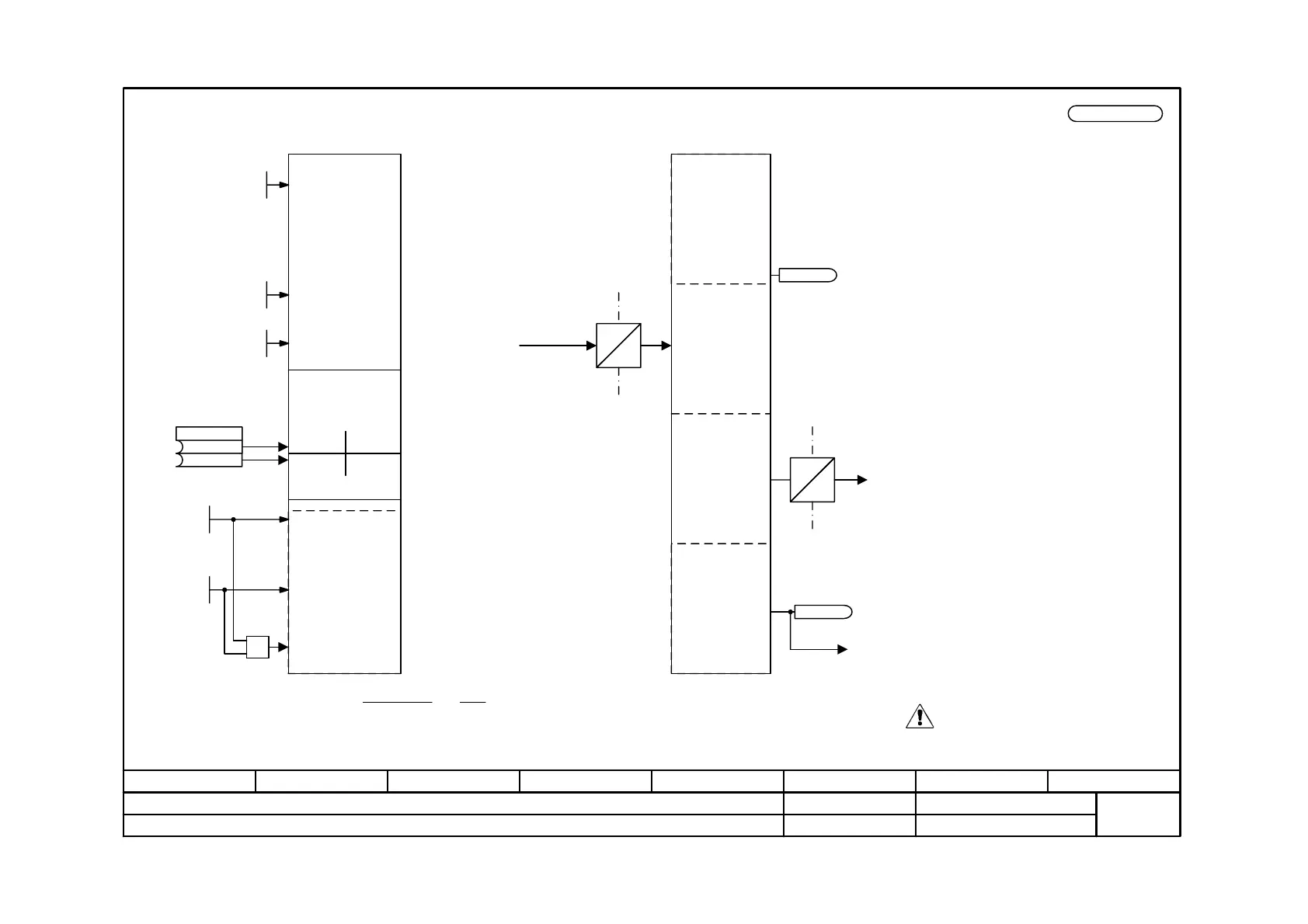
Function diagram
87654321
fp_mc_145_e.vsd
SIMOLINK Board (SLB) 2
MASTERDRIVES MC
30.08.01
Configuration and diagnosis
-145 -
V2.5
SLB
configuration
General part
Dispatcher-
specific part
Module
address = 0
f
<1>
SLB
diagnosis
O
E
Receive
SIMOLINK
telegram a for time=sµ6.36 ;
P745
1
)2
µs 6.36
sµ 3.18+P746
(= nodes addressed of Number :f ⋅−
E
O
Transmit
<1>
(3.18 due to rounding off)
A004
Start alarm SLB2
SIMOLINK
<2> Number of channels = number of transmission channels (32 bit transmission words) per node, is according to the node which uses the most
transmission channels.
<2>
.01
.02
1
0
0
0
SLB in
lower slot
SLB in
higher
slot
Select active SLB
0 = SLB is source for
synchronization
When SIMOLINK is used, telegram failure
monitoring should always be activated!
For the SLB telegram failure time
P741 = 4* P746 (SLB bus cycle time) is
recommended.
This formula only applies if no special data (FD 160a) have been connected
2. Inactive SIMOLINK Board
SLB NodeAddr
0 ... 200
P740.2 (1)
SLB Trns Power
1 ... 3
P742 (3)
SLB # Nodes
0 ... 255
P743.2 (0)
B0047
SLB2 Time out
B0048 SLB2 Start
n959.20 = 7
SLB Channel #
1 ... 8
P745.2 (2)
SLB Cycle Time
0.20 ... 6.50 ms
P746.2 (3.20)
B
P744
Source SYNC Select
B
 Loading...


