Function diagram
87654321
fp_mc_160_e.vsd
SIMOLINK board
MASTERDRIVES MC
23.10.02
Transmitting
-160 -
V2.5
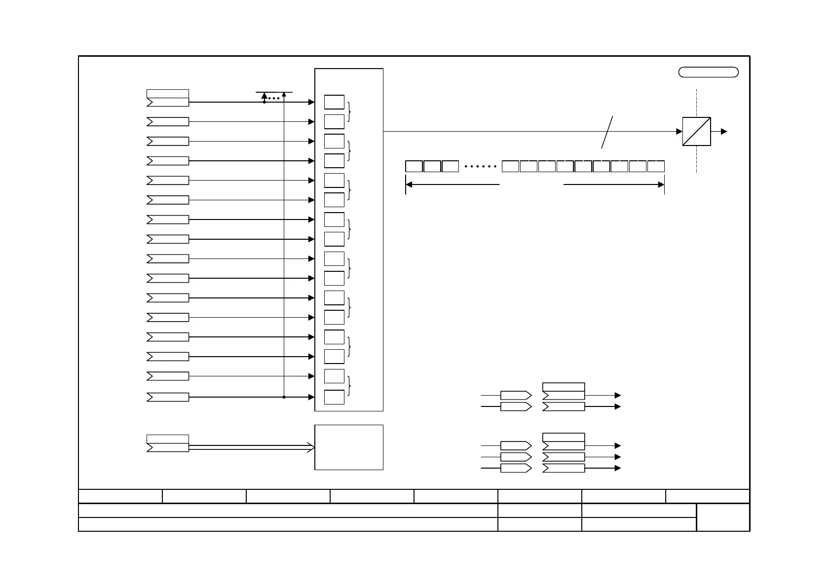
Transmit words
1
2
3
4
6
5
7
8
9
10
11
12
13
14
15
16
.01
.02
.03
.04
.05
.06
.07
.08
.09
.10
.11
.12
.13
.14
.15
.16
Transmitting 32-bit words:
If the same double-word connector is connected up to two successive connector
indices, this is transferred as a 32 bit word.
Examples:
2.
1.
Only the high part of KK1000
and KK2000 is transmitted
as a 16-bit word.
.02
.03
.04
KK1000 is transmitted as
a 32-bit word
.02
.03
Transmit
E
O
SIMOLINK
Bus cycle
(example for 3 nodes and 2 channels)
Bus cycle time
Pause SYNC
NOP 2W 2W2W2W2W2W2W2WNOP
3.1 3.0 2.1 2.0 1.1 1.0 0.1 0.0
- Each module can read out all circulating telegrams.
- Each telegram consists of 2 words = 2 x 16 bits.
- Each module can only write the telegrams of its own module address.
- In the above example, module 1 can write telegrams 1.0 and 1.1.
- The dispatcher (module address 0) provides the SYNC signal after the defined bus cycle time.
- The number of nodes is determined by establishing the bus cycle time and the number of channels per module.
- The dispatcher transmits as many telegrams with ascending node addresses and channel numbers as the
bus cycle time permits.
- If the total number of telegrams requires less time than the bus cycle time, the time up to the SYNC signal
is filled with NOP (No Operation) telegrams.
- The total number of telegrams (modules x channels) is limited to 1023, including pause and SYNC.
Channel 0
Channel 1
Channel 2
Channel 3
Channel 4
Channel 5
Channel 6
Channel 7
Node 1
Transmit words 3 and 4
TxD
Special data
4 double words
.01 ... 08
see function diagram 160a
K
P751 (0)
SrcSLBTrnsData
K
K
K
K
K
K
K
K
K
K
K
K
K
K
K
SLB TrnsData
r752.01 to .16
2000
P751 (0)
1000
KK2000
KK1000
900KK0900
1000
P751 (0)
1000
KK1000
KK1000
n959.21 = 2
K
P756 (0)
 Loading...


