Commissioning Manual
114 6FC5397-4EP10-0BA8, 07/2018
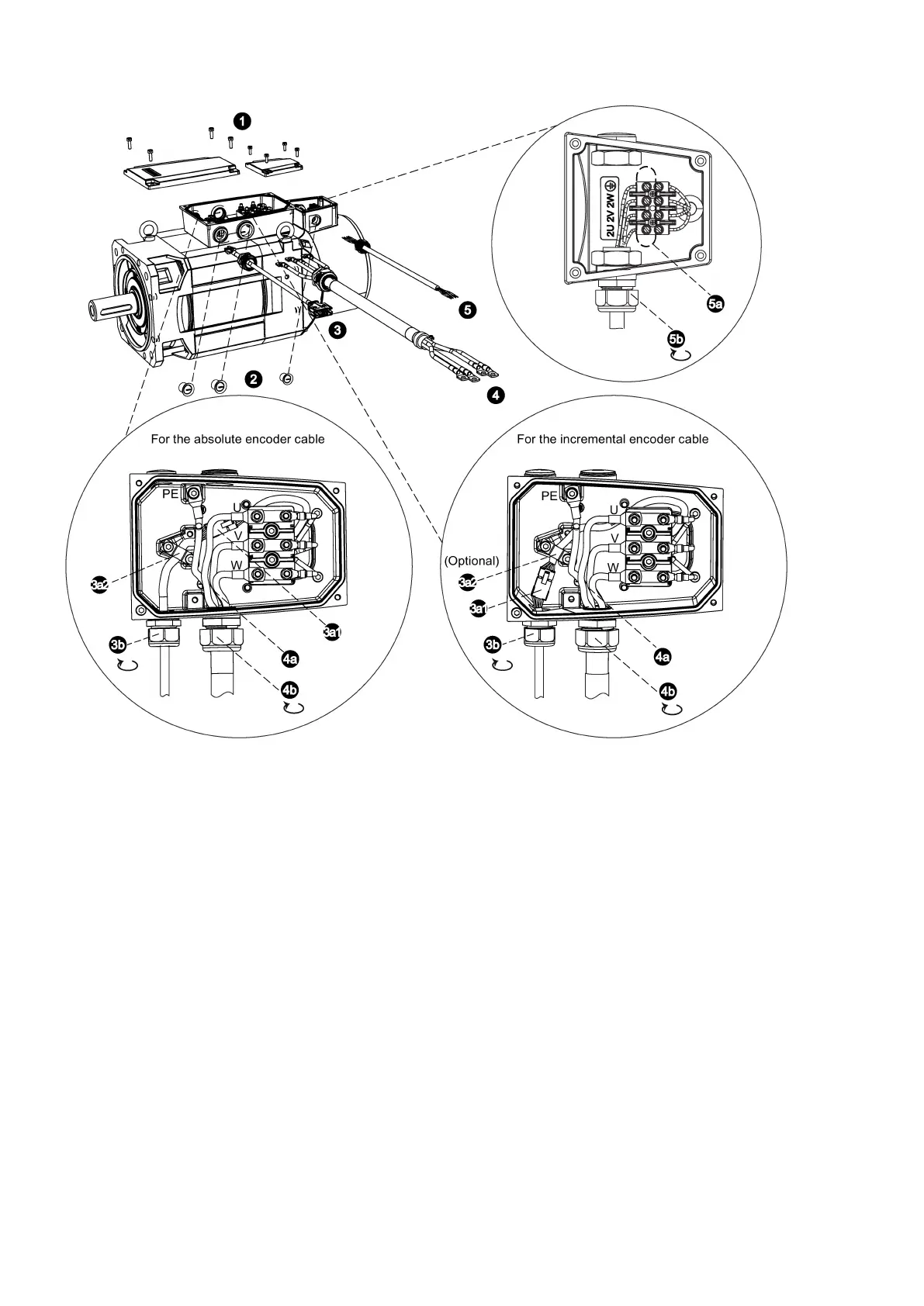
Loosen the screws on the top of both the motor terminal box and the fan terminal box to remove the te
rminal box
Remove the three screw plugs on one side of the two terminal boxes.
e cable gland pre-assembled on the encoder cable. Pass the encoder cable through the first threaded hole
in the motor terminal box housing. Follow the steps below to connect the encoder cable to the motor terminal box:
For the absolute encoder cable:
Insert the male connector of the absolute encoder cable into the female connector in the motor terminal box.
Remove from the terminal box the grounding screws as well as the hose clamp. Lay the absolute encoder cable a
p-
propriately. Place the hose
clamp onto the cable shield, and then tighten the screws. You can select to fix the cable in
the desired direction by screwing the hose clamp at any two of the three screw holes.
For the incremental encoder cable:
Insert the male connector of the incremental encoder cable into the female connector in the motor terminal box.
(Optional) You can select to fix the cable in the desired direction by screwing the hose clamp at any two of the three
screw holes. For detailed information about how to fi
x the cable, see step 3a2 for connecting the absolute encoder
Tighten the cable gland of the encoder cable onto the threaded hole.
Pass the power cable through the cable gland, and then through the second threaded hole in th
e motor terminal box
housing. Follow the steps below to connect the power cable to the motor terminal box:

 Loading...


