Commissioning Manual
118 6FC5397-4EP10-0BA8, 07/2018
Note
When you run a servo motor with an incremental encoder in JOG mode, the servo motor mak
es a short buzzing sound
indicating that it is identifying the magnetic pole position of the rotor.
Configuring Drive Bus addresses
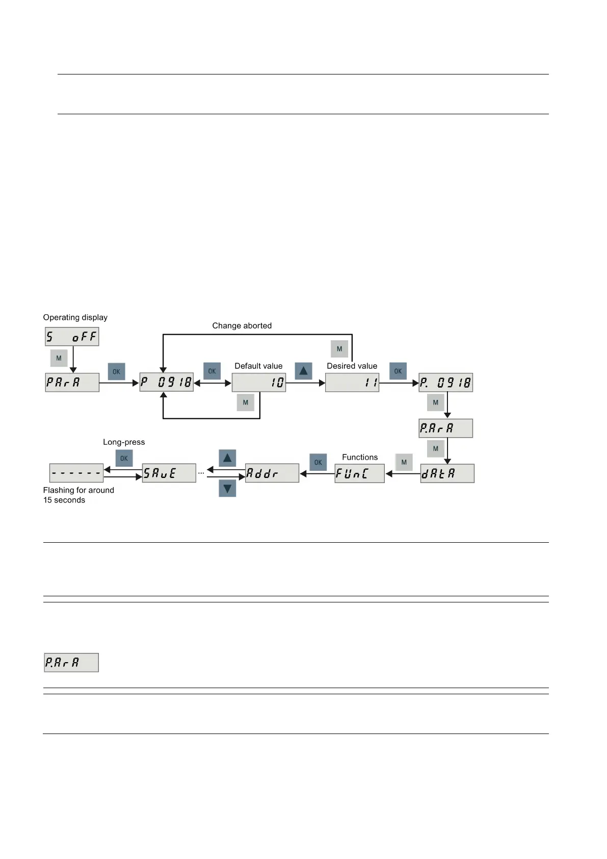
To configure the Drive Bus addresses on the SINAMICS V70 drive, set parameter p0918 (default = 10) with the drive BOP
as required. You must set a proper address according to the actual application of the drive.
● 11: X axis
● 12: Y axis (or additional axis for the turning variant of the control system)
● 13: Z axis
● 14: Digital spindle (SINAMICS V70 spindle drive only)
● 15: Additional axis 1 *
● 16: Additional axis 2 *
* Note that Drive Bus addresses 15 and 16 are not supported on the control system with PPU15x.3. In addition, to use Drive
Bus address 16, the drive firmware version must be 1.05.00.02 or higher.
You can also set the Drive Bus address with the auxiliary function menu on the drive BOP. For more information, see
Section "Setting Drive Bus address (Page 449)".
Note
Do not switch on the 24
VDC power supply for the SINUMERIK 808D ADVANCED before you finish setting the Drive Bus
addresses for all connected drives.
After setting a proper address, you must save the parameter and then restart the drive to apply your setting.
Note
After the Drive Bus communication is established for the first time, the internal commun
ication parameters are automatically
changed and hence a dot appears on the display as follows:
You must perform a save operation to remove the dot.
er the Drive Bus communication is established, the BOP is protected from any operation except clearing alarms and

 Loading...


