Commissioning Manual
138 6FC5397-4EP10-0BA8, 07/2018
Note
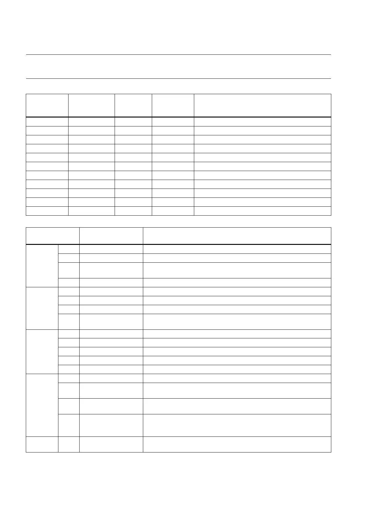
The following tables list the PLC machine data used in the default PLC applications. The machine data not listed below is
reserved for the manufacturer.
USER_DATA_INT
MD14510
Machine data -
Integer
Layout of the traverse keys
Spindle override 50% key holding on time defined
Spindle override 100% key holding on time defined
Feedrate override 0% key holding on time defined
Feedrate override 100% key holding on time defined
14510[22] DB4500.DBW44 0.1 s 30 to 200 Monitoring time when searching for tools
USER_DATA_HEX
MD14512
Machine data - Hex
14512[16] Bit 1 DB4500.DBX1016.1 Function of chip conveyor (milling)
Function of safety door (milling)
Bit 3 DB4500.DBX1016.3 When the function of safety door is active, it can be triggered by M01/M02
(milling)
Handwheel assignment with the MCP/HMI
14512[17]
Turret (turning); tool magazine (milling)
Clamping function (turning)
Tail stock function (turning)
Bit 3 DB4500.DBX1017.3 Selection between handwheel and hand-held unit (0: handwheel; 1: hand-
14512[18]
Automatic lubrication at power-on
External signal for spindle stop
The hardware limit is independent from a PLC program
Each feed axis has a hardware limit switch (activated when Bit 6 = 0)
14512[19]
Function of spindle braking
Bit 2 DB4500.DBX1019.2 Password clearing by power-on (0: delete the password; 1: do not delete
Bit 4 DB4500.DBX1019.4 Spindle speed selection in "JOG" mode (0: select the speed set in
MD32020; 1: select the speed set last time)
Bit 7 DB4500.DBX1019.7 Manual machine function (this function becomes active if you have in-
stalled licensed turning machine system and called it with a PLC subrou-
14512[20] Bit 0 DB4500.DBX1020.0 Grey coded switch (0: spindle override controlled by the grey code; 1:
spindle override controlled by triggering user keys)

 Loading...


