Commissioning Manual
6FC5397-4EP10-0BA8, 07/2018
233
Measurement functions
11.1
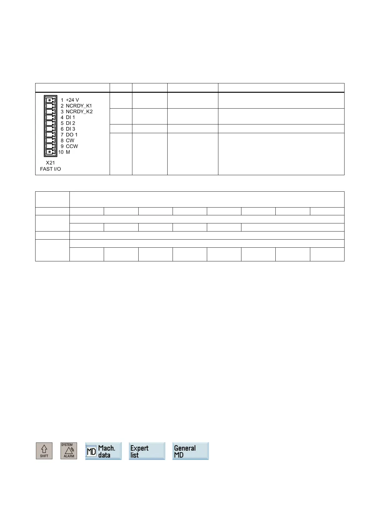
The fast input/output interface (X21) provides 3 digital inputs and 1 digital output:
4 DI1 $A_IN[1] Fast input with address DB2900.DBX0.0, for
5 DI2 $A_IN[2] Fast input with address DB2900.DBX0.1, for
Fast input with address DB2900.DBX0.2
7 DO1 $A_OUT[1] Fast output with address DB2900.DBX4.0
Signals from fast inputs and outputs [r]
NCK → PLC interface
Actual value for digital NCK inputs
Setpoint for digital NCK outputs
Output 8 Output 7 Output 6 Output 5 Output 4 Output 3 Output 2 Hardware
●
In the PLC application program, you can directly read each bit value from the address DB2900. In a part program, you
can read the fast input value via system variable $A_IN[x].
●
From the address DB2900.DBX4.0 you cannot assign a value to the fast output; otherwise, the PLC application program
will stop with an error. However, you can assign a value to the fast output from address DB2800.DBX5.0 and
DB2800.DBX6.0.
In the PLC application program, you can trigger the address DB2800.DBX5.0 with a rising edge or a negative edge at the
address DB2800.DBX6.0, and thus the address DB2900.DBX4.0 will vary with the address DB2800.DBX6.0.
The first probe is connected to pin 4 (DI1) and the second probe to pin 5 (DI2) of interface X21. For the probe, use an
external voltage (24 V) whose reference potential should be connected to X21 pin 10
The following machine data should be checked and adjusted if necessary:
● MD13200[0] $MN_MEAS_PROBE_LOW_ACTIVE = 0 or 1
● MD13200[1] $MN_MEAS_PROBE_LOW_ACTIVE = 0 or 1
– Value 0 = deflected state 24 V (default)
– Value 1 = deflected state 0 V
You can access this machine data through the following operations:
+ → → →

 Loading...


