Commissioning Manual
6FC5397-4EP10-0BA8, 07/2018
89
Connecting
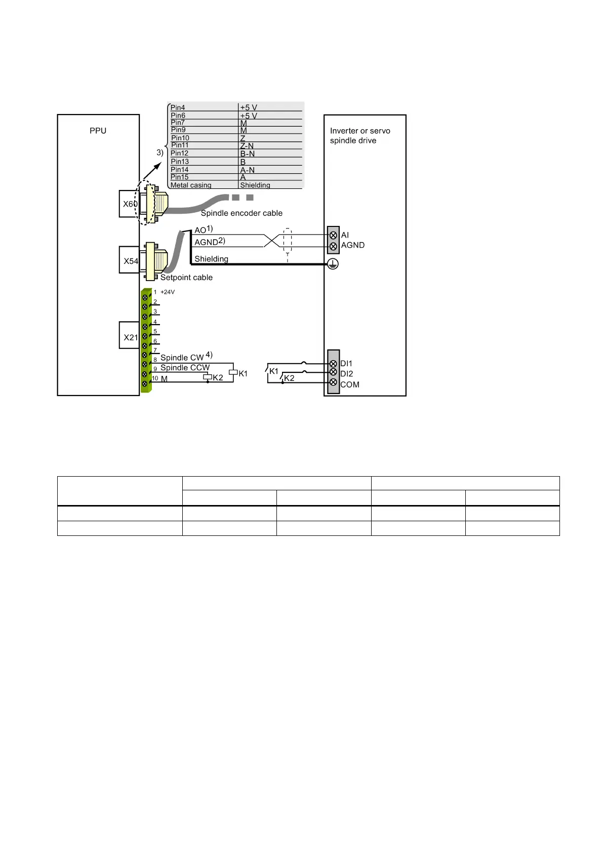
Connecting the inverter or servo spindle drive (unipolar)
1)
10 V analog voltage
2)
0 V signal
3)
Use twisted pair cables for signals A/A_N, B/B_N, Z/Z_N, and +5 V/M.
4)
See the following table for the enable status of pin 8 and pin 9 when the spindle rotates clockwise or counter-clockwise
respectively for unipolar 1 and unipolar 2.

 Loading...


