Manual Close Mode (phases, ground)
When a circuit breaker is closed onto a faulted line, a high speed trip by the circuit breaker is often desired. For
overcurrent or high-set element the delay may be bypassed via a Manual Close pulse, thus resulting in instan-
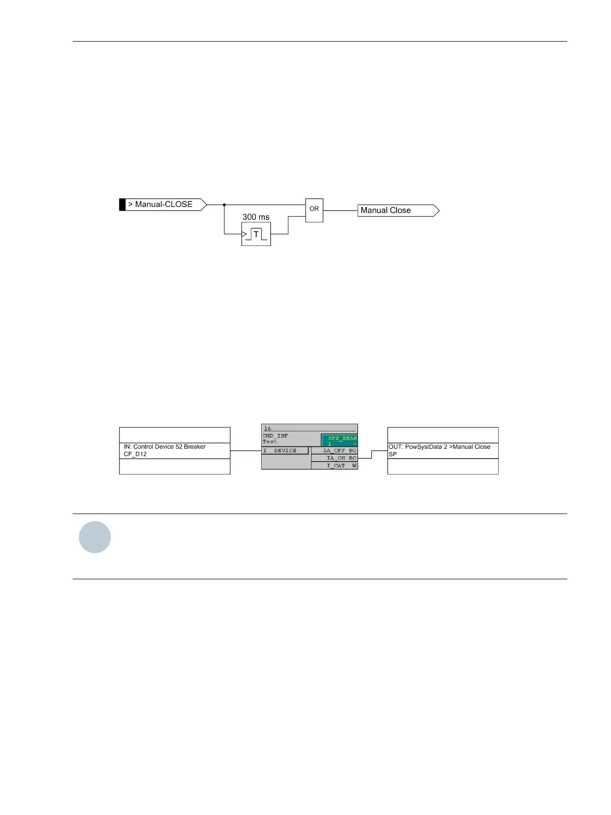
taneous tripping. The internal "Manual close" signal is built from the binary input signal
>Manual Close
(no.
356). The internal "Manual close" signal remains active as long as the binary input signal
>Manual Close
is
active, but at least for 300 ms (see the following logic diagram). To enable the device to react properly on
occurrence of a fault in the phase elements after manual close, address 1513 MANUAL CLOSE has to be set
accordingly. Accordingly, address 1613 MANUAL CLOSE is considered for the ground path address. Thus, the
user determines for both elements, the phase and the ground element, what pickup value is active with what
delay when the circuit breaker is closed manually.
[lo_7sj6-hand-ein, 1, en_US]
Figure 2-36 Manual close feature
External Control Switch
If the manual close signal is not from the 7SJ62/64 device, that is, neither sent via the built-in operator inter-
face nor via a serial port but directly from a control acknowledgment switch, this signal must be passed to a
7SJ62/64 binary input, and configured accordingly (
>Manual Close
), so that the element selected for
MANUAL CLOSE can become effective. Inactive means that all elements (phase and ground) operate with
the configured trip times even with manual close.
Internal Control Function
The manual closing information must be allocated via CFC (interlocking task-level) using the CMD_Information
block, if the internal control function is used.
[handein-260602-kn, 1, en_US]
Figure 2-37 Example for the generation of a manual close signal using the internal control function
NOTE
For an interaction between the automatic reclosing function (79 AR) and the control function, an extended
CFC logic is necessary. See margin heading “Close command: Directly or via Control” in the Setting Notes of
the automatic reclosing function (Section 2.16.6 Setting Notes).
Interaction with Automatic Reclosure Function (phases)
When reclosing follows, high-speed protection against faults with 67-2 or 67-3 is usually desired. If the fault
still exists after reclosing, the 67-1 or 67-TOC element will be initiated with graded tripping times, that is, the
67-2 or 67-3 element will be blocked. You can use parameter 1514 67-2 active or 1532 67-3 active
active to define whether the 67-2 or 67-3 element is influenced by a release signal of the internal or an
external automatic reclosing device or not. The setting with 79 active means that the 67-2 or 67-3
element is only released if the automatic reclosing function is not blocked. If this is not desired, the setting
always is selected so that the 67-2 or 67-3 element is always active as configured.
The integrated automatic reclosing function of 7SJ62/64 also provides the option to individually determine for
each overcurrent element whether tripping or blocking is to be carried out instantaneously, unaffected by the
AR with time delay (see Section 2.16 Automatic Reclosing System 79).
Functions
2.3 Directional Overcurrent Protection 67, 67N
SIPROTEC 4, 7SJ62/64, Manual 105
C53000-G1140-C207-8, Edition 08.2016

 Loading...


