The dropout curve may be user-defined as well. This is advantageous when the overcurrent protection must
be coordinated with conventional electromechanical overcurrent relays located towards the source. If no user-
defined dropout curve is required, the element drops out as soon as the measured signal is less than approx.
95% of the pickup setting. When a new pickup is evoked, the timer starts at zero again.
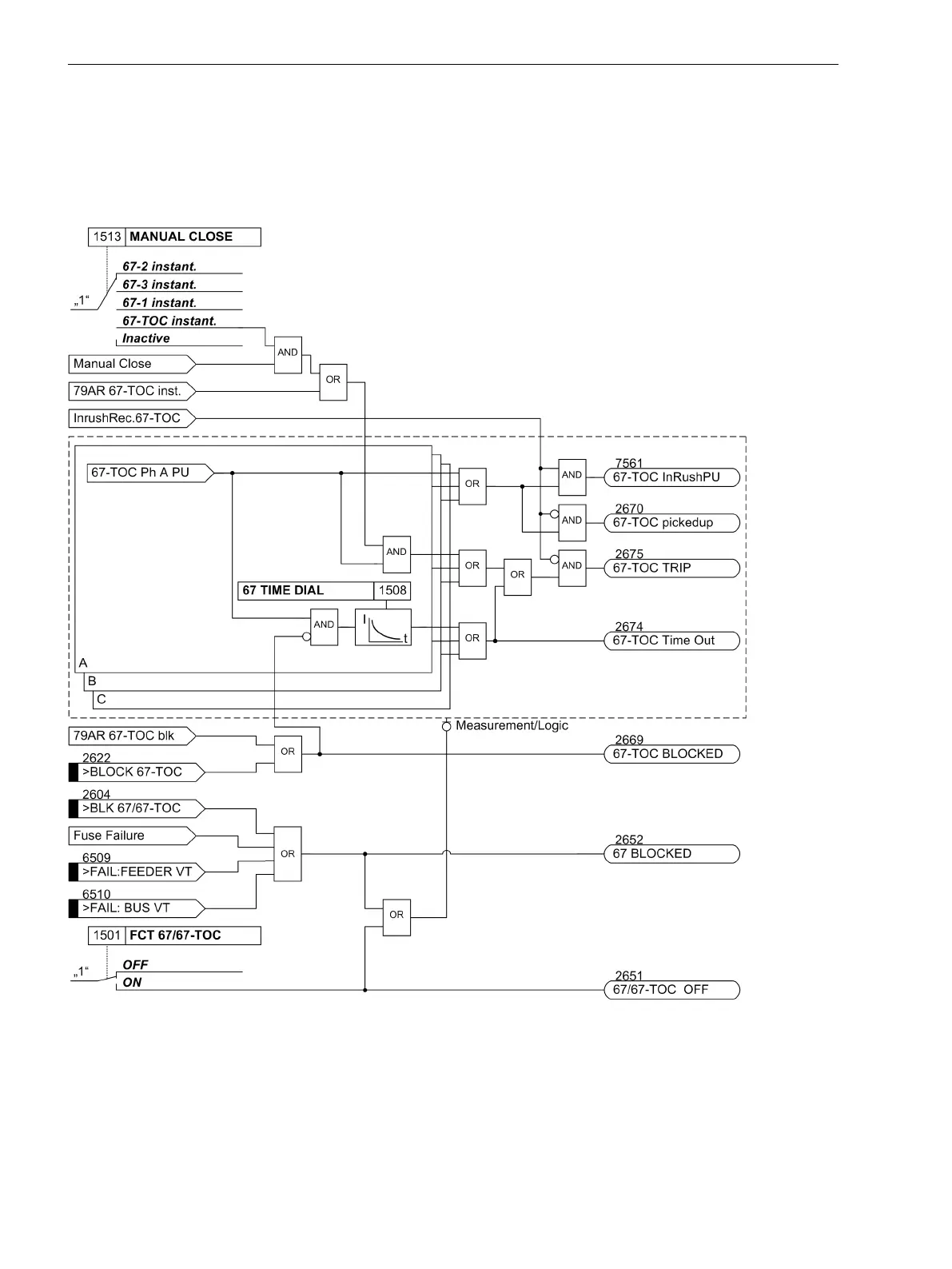
The following figure shows by way of an example the logic diagram for the 67-TOC relay element of the direc-
tional inverse time overcurrent protection of the phase currents.
[7sj6x_gerueberstromzeit_abh_ueberstrom_ip-150502-kn, 1, en_US]
Figure 2-27
Logic diagram for the directional overcurrent protection: 67-TOC relay element
Interaction with Fuse Failure Monitor (FFM)
False or undesired tripping can be caused by a measuring voltage that can be caused by either short-circuit or
broken wire in the voltage transformer's secondary system or an operation of the voltage transformer fuse.
2.3.5
Functions
2.3 Directional Overcurrent Protection 67, 67N
92 SIPROTEC 4, 7SJ62/64, Manual
C53000-G1140-C207-8, Edition 08.2016

 Loading...


