[7sj80-ueberspgs-schutz-20061219, 1, en_US]
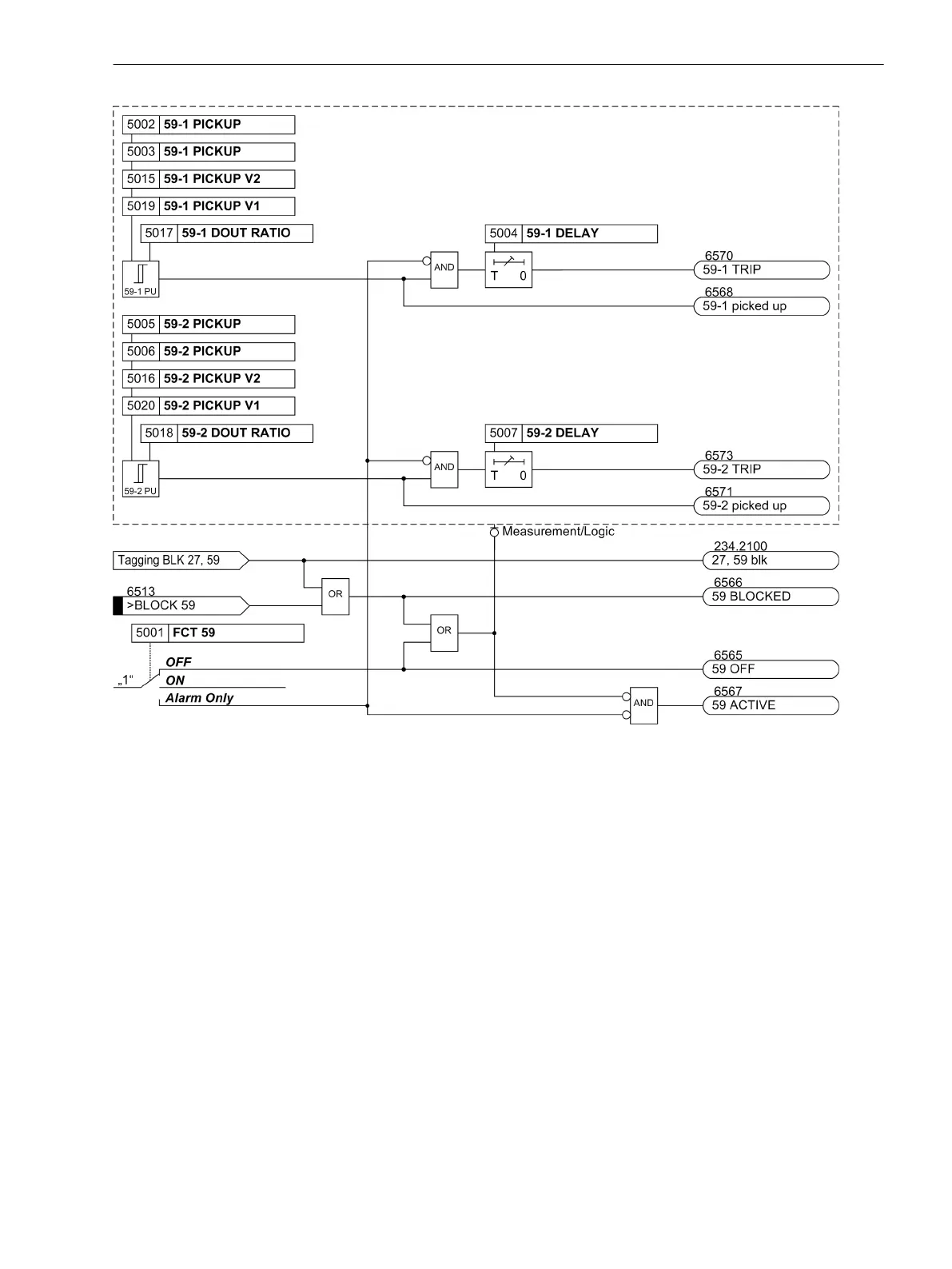
Figure 2-48
Logic diagram of the overvoltage protection
Undervoltage Protection 27
Function
Undervoltage protection consists of two definite time elements (27-1 PICKUP and 27-2 PICKUP). There-
fore, tripping can be time-coordinated depending on how severe voltage collapses are. Voltage thresholds and
time delays can be set individually for both elements.
The dropout ratio for the two undervoltage elements (= V
dropout value
/V
pickup value
) can be set.
Figure 2-49 shows a typical voltage profile during a fault for source side connection of the voltage trans-
formers. Because full voltage is present after the circuit breaker has been opened, current supervision CS
described above is not necessary in this case. After the voltage has dropped below the pickup setting, tripping
is initiated after time delay 27-1 DELAY. As long as the voltage remains below the dropout setting, reclosing
is blocked. Only after the fault has been cleared, i.e. when the voltage increases above the dropout level, the
element drops out and allows reclosing of the circuit breaker.
2.6.3
Functions
2.6 Voltage Protection 27, 59
SIPROTEC 4, 7SJ62/64, Manual 129
C53000-G1140-C207-8, Edition 08.2016

 Loading...


