Pre-defined CFC Charts
Some CFC charts are already supplied with the SIPROTEC device. Depending on the variant the following
charts may be implemented:
Device and System Logic
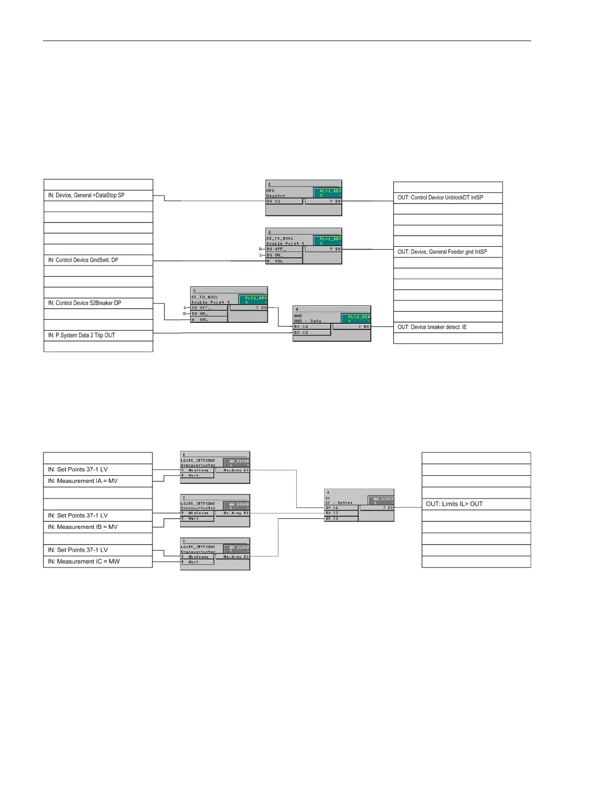
The NEGATOR block assigns the input signal “DataStop” directly to an output. This is not directly possible
without the interconnection of this block.
[cfc-verbindungen-eingang-ausgang-020902-kn, 1, en_US]
Figure E-6 Logical links between input and output
Setpoints MV
Using modules on the running sequence ”measured value processing", a low current monitor for the three
phase currents is implemented. The output message is set high as soon as one of the three phase currents falls
below the set threshold:
[cfc-unterstromueberwachung-020313-kn, 1, en_US]
Figure E-7 Undercurrent monitoring
Blocks of the task level "MW_BEARB" (measured value processing) are used to implement the overcurrent
monitoring and the power monitoring.
E.6
Default Settings and Protocol-dependent Functions
E.6 Pre-defined CFC Charts
608 SIPROTEC 4, 7SJ62/64, Manual
C53000-G1140-C207-8, Edition 08.2016

 Loading...


