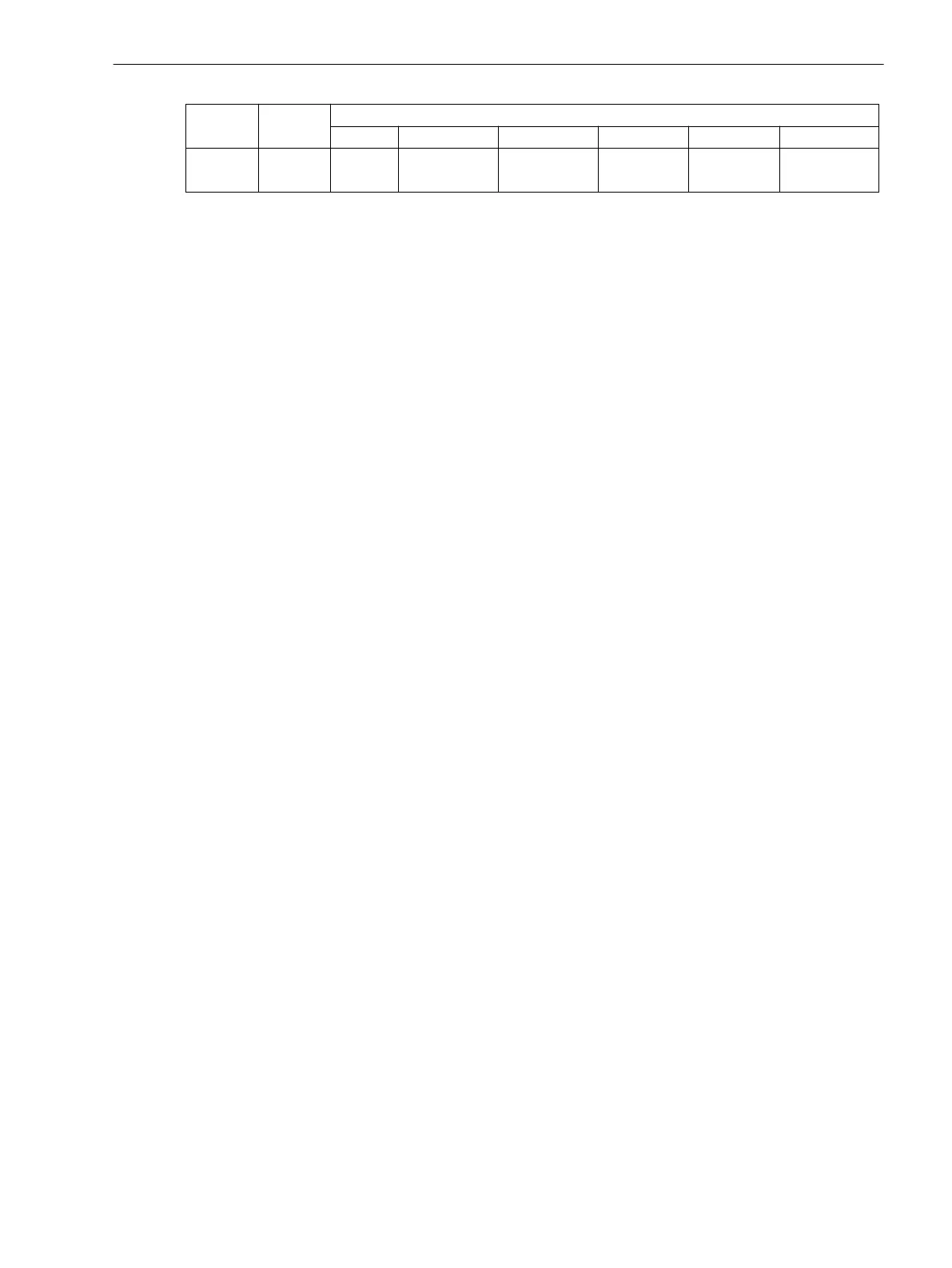
Device Housing Module Slot Position
I/5 I/19 I/33 II/5 II/19 II/33
7SJ647 1/1 C-CPU2 B-I/O2
Addr. 5
C-I/O4
Addr. 7
B-I/O2
Addr. 6
C-I/O11
Addr. 3
Software Monitoring
Watchdog
For continuous monitoring of the program sequences, a time monitor is provided in the hardware (hardware
watchdog) that expires upon failure of the processor or an internal program, and causes a complete restart of
the processor system.
An additional software watchdog ensures that malfunctions during the processing of programs are discov-
ered. This also initiates a restart of the processor system.
If such a malfunction is not cleared by the restart, an additional restart attempt is begun. After three unsuc-
cessful restarts within a 30 second window of time, the device automatically removes itself from service and
the red “Error” LED lights up. The readiness relay drops out and indicates „device malfunction“ with its normally
closed contact.
Offset Monitoring
This monitoring function checks all ring buffer data channels for corrupt offset replication of the analog/digital
transformers and the analog input paths using offset filters. Possible offset errors are detected using DC filters,
and the associated sampled values are corrected up to a specific limit. If this limit is exceeded, an indication is
generated (191
Error Offset
) and integrated into the warning group indication (160). As increased offset
values impair the measurements, we recommend sending the device to the OEM plant for corrective action
should this indication persist.
The Offset monitoring can be blocked via the binary input signal
>Blk.offset s.
(No. 17565).
Monitoring of the Transformer Circuits
Open circuits or short circuits in the secondary circuits of the current and voltage transformers, as well as
faults in the connections (important during commissioning!), are detected and reported by the device. The
measured quantities are periodically checked in the background for this purpose, as long as no system fault is
present.
Current Symmetry
During normal system operation, symmetry among the input currents is expected. The monitoring of the
measured values in the device checks this balance. The smallest phase current is compared to the largest
phase current. Asymmetry is detected if | Ιmin | / | Ιmax | < BAL. FACTOR I as long as Ιmax > BALANCE I
LIMIT is valid.
Thereby Ιmax is the largest of the three phase currents and Imin the smallest. The symmetry factor BAL.
FACTOR I (address 8105) represents the allowable asymmetry of the phase currents while the limit value
BALANCE I LIMIT (address 8104) is the lower limit of the operating range of this monitoring (see
Figure 2-71). Both parameters can be set. The dropout ratio is about 97 %.
This fault is signalled after settable delay time with
Fail I balance
.
2.12.1.4
2.12.1.5
Functions
2.12 Monitoring Functions
SIPROTEC 4, 7SJ62/64, Manual 183
C53000-G1140-C207-8, Edition 08.2016

 Loading...


