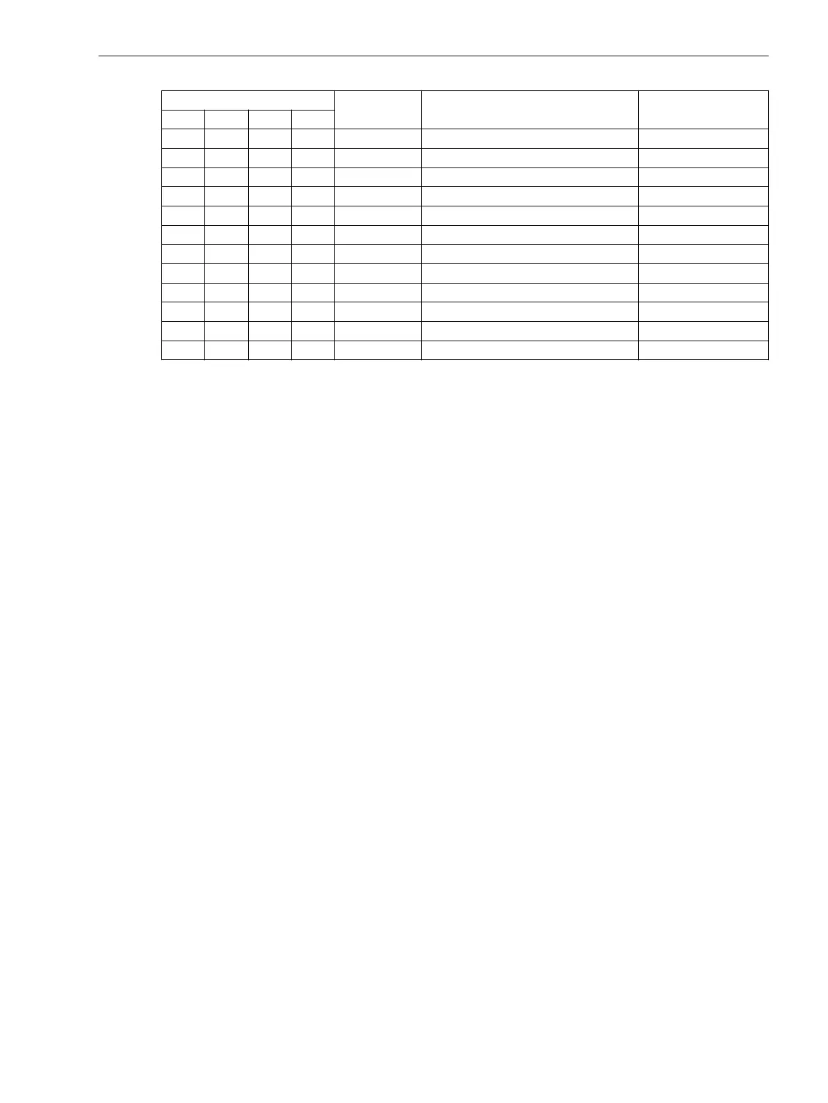
Pickup by Fault Type Measured Loop Signaled Loop
A B C N
x N A-N, B-N, C-N signaled loop
x x A-N A-N A-N
x x B-N B-N B-N
x x C-N C-N C-N
x x A-B A-B A-B
x x A-C A-C A-C
x x B-C B-C B-C
x x x A-B-N A-B, A-N, B-N signaled loop
x x x A-C-N C-A, A-N, B-N signaled loop
x x x B-C-N B-C, B-N, C-N signaled loop
x x x A-B-C A-B, B-C, C-A signaled loop
x x x x A-B-C-N A-B, B-C, C-A, A-N, B-N, C-N signaled loop
Output of Fault Location
The following information is output as result of the fault location:
•
the short-circuit loop from which the fault reactance was determined,
•
the fault reactance X in Ω primary and Ω secondary,
•
the fault resistance R in Ω primary and Ω secondary,
•
the distance to fault d in kilometers or miles of the line proportional to the reactance, converted on the
basis of the set line reactance per unit line length,
•
the distance to fault d in % of the line length, calculated on the basis of the set reactance per unit length
and the set line length.
Line Sections
The line type is determined by the line section settings. If, for instance, the line includes a cable and an over-
head line, two different sections must be configured. The system can distinguish between up to three
different line types. When configuring this line data, please note that the different tabs for setting the line
sections will only be displayed if more than one line section has been configured under the functional scope
(address 181). The parameters for a line section are entered in the Setting tab .
.
Setting Notes
General
The fault location is only enabled if address 180 was set to Enabled during configuration of the function
extent.
Under address 181 L-sections FL the number of line section must be selected, which is required for the
accurate description of the line. If the number is set to 2 Sections or 3 Sections, further setting sheets
appear in the Power System Data 2 in DIGSI. Default setting is 1 Section.
Line Data
To calculate the fault distance in kilometers or miles, the device needs the per distance reactance of the line in
Ω/kilometer or Ω/mile. Furthermore, the line length in km or miles, the angle of the line impedance, and
resistance and reactance ratios are required. These parameters have already been set in the Power System
Data 2 for a maximum of 3 line sections (see Section 2.1.6.2 Setting Notes under “Ground Impedance Ratios”
and “Reactance per Unit Length”).
2.17.2
Functions
2.17 Fault Locator
SIPROTEC 4, 7SJ62/64, Manual 261
C53000-G1140-C207-8, Edition 08.2016