active means that the 50-2 or the 50-3 element will only be released if automatic reclosing is not blocked. If
this is not desired, the setting Always is selected so that the 50-2 or the 50-3 element is always active.
The integrated automatic reclosing function of 7SJ62/64 also provides the option to individually determine for
each overcurrent element whether tripping or blocking is to be carried out instantaneously or unaffected by
the AR with the set time delay (see Section 2.16 Automatic Reclosing System 79).
Interaction with the Automatic Reclosing Function (ground)
When reclosing occurs, it is desirable to have high-speed protection against faults with 50N-2 or 50N-3. If the
fault still exists after the first reclosing, the 50N-1 or the 51N element will be initiated with coordinated trip-
ping times, that is, element 50N-2 or 50N-3 will be blocked. At address 1314 50N-2 active or 1316 50N-3
active active it can be specified whether the 50N-2 or the 50N-3 element should be influenced by the
release signal of an internal or external automatic reclosing system. Address with 79 active determines
that the 50N-2 or the 50N-3 element will only operate if automatic reclosing is not blocked. If not desired,
select the setting Always so that the 50N-2 or the 50N-3 element will always operate, as configured.
The integrated automatic reclosing function of 7SJ62/64 also provides the option to individually determine for
each overcurrent element whether tripping or blocking is to be carried out instantaneously or unaffected by
the AR with the set time delay (see Section 2.16 Automatic Reclosing System 79).
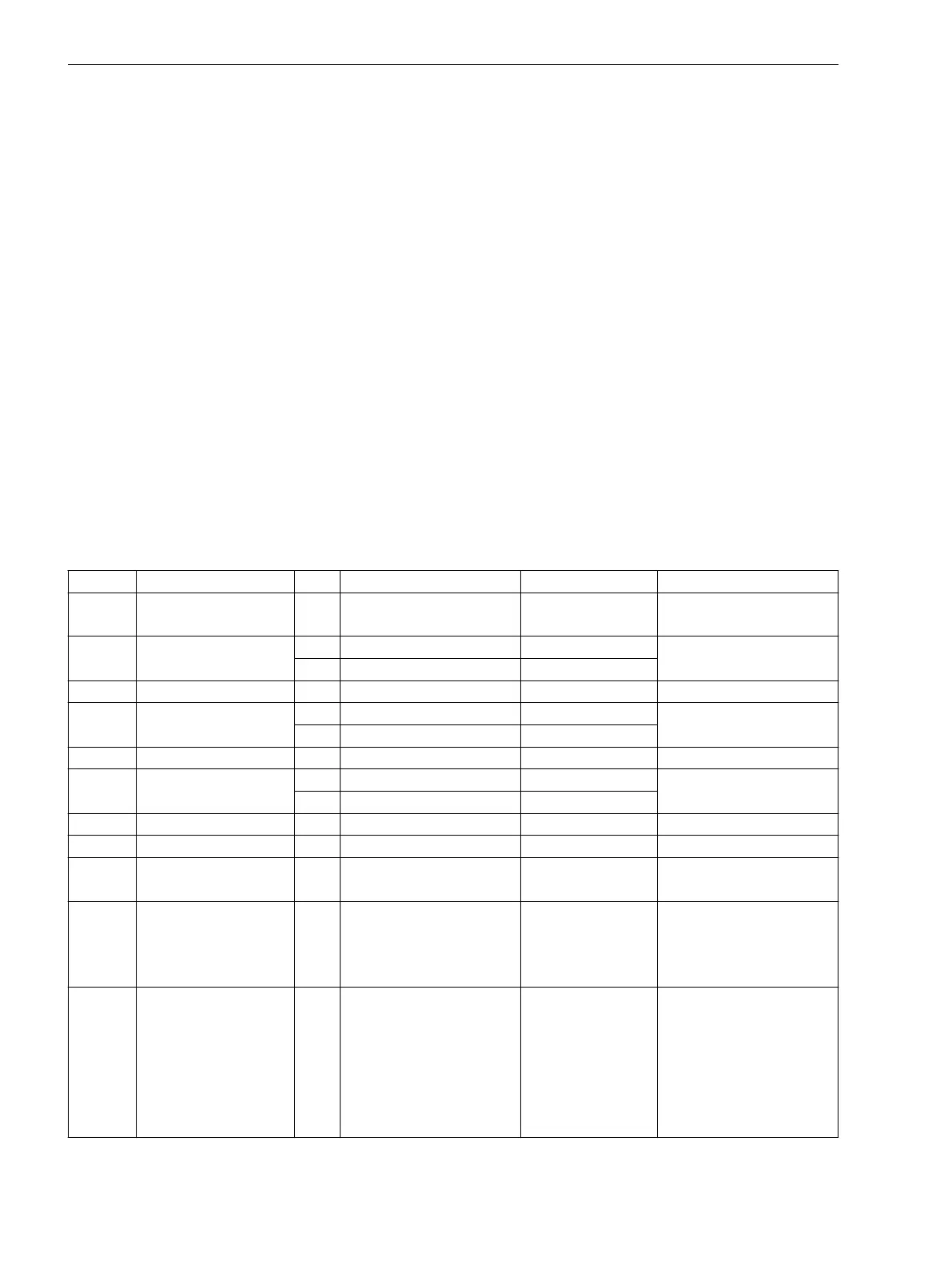
Settings
Addresses which have an appended “A” can only be changed with DIGSI, under “Additional Settings”.
The table indicates region-specific presettings. Column C (configuration) indicates the corresponding secon-
dary nominal current of the current transformer.
Addr.
Parameter C Setting Options Default Setting Comments
1201 FCT 50/51 ON
OFF
ON 50, 51 Phase Time Overcur-
rent
1202 50-2 PICKUP 1A 0.10 .. 35.00 A; ∞ 2.00 A 50-2 Pickup
5A 0.50 .. 175.00 A; ∞ 10.00 A
1203 50-2 DELAY 0.00 .. 60.00 sec; ∞ 0.00 sec 50-2 Time Delay
1204 50-1 PICKUP 1A 0.10 .. 35.00 A; ∞ 1.00 A 50-1 Pickup
5A 0.50 .. 175.00 A; ∞ 5.00 A
1205 50-1 DELAY 0.00 .. 60.00 sec; ∞ 0.50 sec 50-1 Time Delay
1207 51 PICKUP 1A 0.10 .. 4.00 A 1.00 A 51 Pickup
5A 0.50 .. 20.00 A 5.00 A
1208 51 TIME DIAL 0.05 .. 3.20 sec; ∞ 0.50 sec 51 Time Dial
1209 51 TIME DIAL 0.50 .. 15.00 ; ∞ 5.00 51 Time Dial
1210 51 Drop-out Instantaneous
Disk Emulation
Disk Emulation Drop-out characteristic
1211 51 IEC CURVE Normal Inverse
Very Inverse
Extremely Inv.
Long Inverse
Normal Inverse IEC Curve
1212 51 ANSI CURVE Very Inverse
Inverse
Short Inverse
Long Inverse
Moderately Inv.
Extremely Inv.
Definite Inv.
Very Inverse ANSI Curve
2.2.12
Functions
2.2 Overcurrent Protection 50, 51, 50N, 51N
80 SIPROTEC 4, 7SJ62/64, Manual
C53000-G1140-C207-8, Edition 08.2016

 Loading...


