NOTE
With inrush detection activated and inrush only on B, no cross blocking will take place in the other phases.
On the other hand, if inrush with cross blocking is activated on A or C, B will also be blocked.
Fast Busbar Protection Using Reverse Interlocking
Application Example
Each of the current elements can be blocked via binary inputs. A setting parameter determines whether the
binary input operates in the normally open (i.e. actuated when energized) or the normally closed (i.e. actu-
ated when de-energized) mode. This allows fast busbar protection to be applied in star systems or open ring
systems by applying "reverse interlocking". This principle is often used, for example, in distribution systems,
auxiliary systems of power plants and similar systems, where a station supply transformer supplied from the
transmission grid serves internal loads of the generation station via a medium voltage bus with multiple
feeders (Figure 2-17).
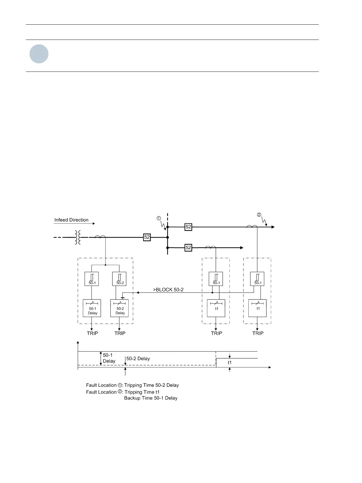
The reverse interlocking principle is based on the following: Time overcurrent protection of the busbar feeder
trips with a short time delay T 50-2 independent of the grading times of the feeders, unless the pickup of the
next load-side overcurrent protection element blocks the busbar protection (Figure 2-17). Always the protec-
tion element nearest to the fault will trip with the short time delay since this element cannot be blocked by a
protection element located behind the fault. Time elements T 50-1 or T51 are still effective as backup
element. Pickup signals output by the load-side protective relay are used as input message
>BLOCK 50-2
via
a binary input at the feeder-side protective relay.
[rueckwverr-150502-kn, 1, en_US]
Figure 2-17
Reverse interlocking protection scheme
2.2.10
Functions
2.2 Overcurrent Protection 50, 51, 50N, 51N
72 SIPROTEC 4, 7SJ62/64, Manual
C53000-G1140-C207-8, Edition 08.2016

 Loading...


