Parameter Address Parameter Address
CT SECONDARY
205
Ignd-CT SEC
218
Vnom PRIMARY
202
Vph / Vdelta
206
Vnom SECONDARY
203
FullScaleVolt.
1101
FullScaleCurr.
1102
Depending on the type of device ordered and the device connections, some of the operational measured
values listed below may not be available.
The phase–to–ground voltages are either measured directly, if the voltage inputs are connected phase–to–
ground, or they are calculated from the phase–to–phase voltages V
A–B
and V
B–C
and the displacement voltage
V
N
.
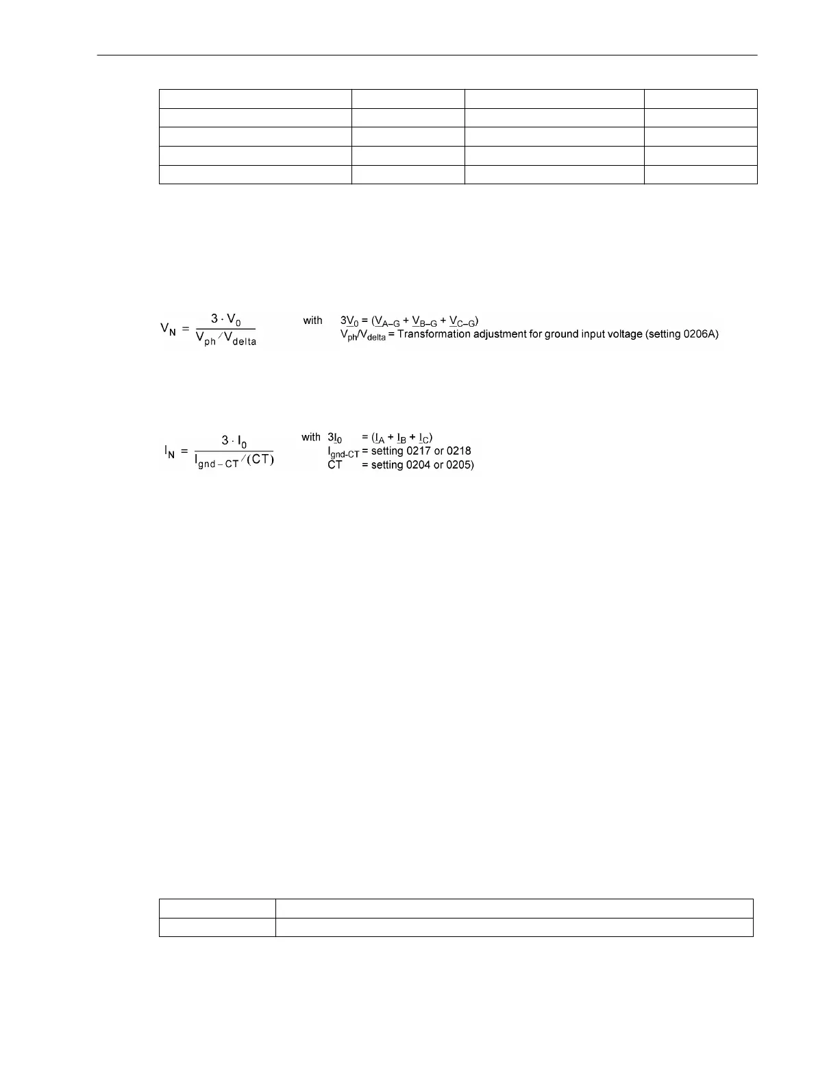
The displacement voltage V
N
is either measured directly or calculated from the phase-to-ground voltages:
[verlagerungsspannunguen-020315-wlk, 1, en_US]
Please note that value V
0
is indicated in the operational measured values.
The ground current Ι
N
is either measured directly or calculated from the conductor currents.
[erdstrom-020315-wlk, 1, en_US]
In addition, the following may be available:
•
Θ/Θ
TRIP
thermal measured value of overload protection value for stator in % of the trip initiating over-
temperature
•
Θ/Θ
L TRIP
thermal measured value of restart inhibit (rotor winding),
•
Θ
Restart
restarting limit of restart inhibit,
•
T
Reclose
total time, before the motor can be restarted,
•
Θ
RTD 1
to Θ
RTD 12
temperature values at the RTD box.
Upon delivery, the power and operating values are set in such manner that power in line direction is positive.
Active components in line direction and inductive reactive components in line direction are also positive. The
same applies to the power factor cosϕ. It is occasionally desired to define the power drawn from the line (e.g.
as seen from the consumer) positively. Using parameter 1108 P,Q sign the signs for these components can
be inverted.
The calculation of the operational measured values is also performed during a fault. The values are updated in
intervals of > 0.3 s and < 1 s.
Transfer of Measured Values
Measured values can be transferred via the interfaces to a central control and storage unit.
The measuring range in which these values are transmitted depend on the protocol and, if necessary, addi-
tional settings.
Protocol
Transmittable measuring range, format
IEC 60870-5-103 0 to 240 % of the measured value.
2.25.3.2
Functions
2.25 Auxiliary Functions
SIPROTEC 4, 7SJ62/64, Manual 331
C53000-G1140-C207-8, Edition 08.2016

 Loading...


