[7sj6x_gerueberstromzeit_hochstromst-030903-he, 1, en_US]
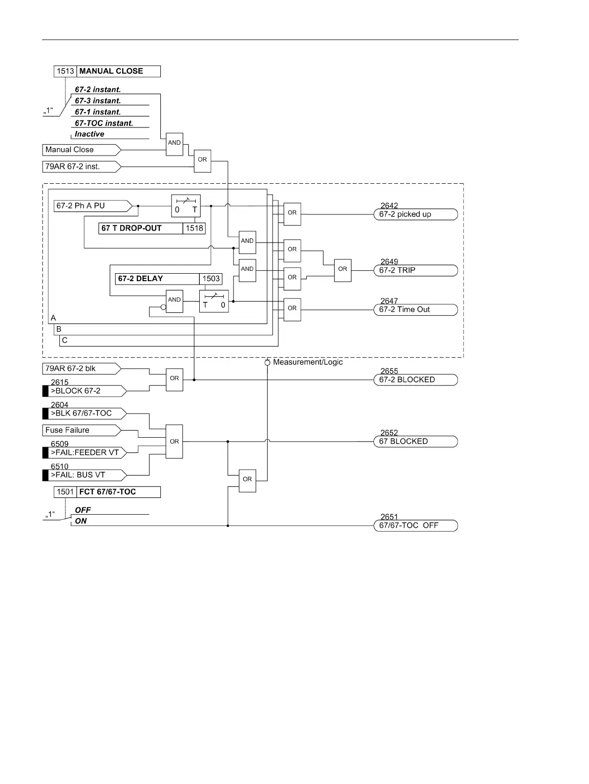
Figure 2-24
Logic diagram for directional high-set element 67-2 for phases
If parameter MANUAL CLOSE is set to 67-2 instant. or 67-3 instant. and manual close detection is
present, a pickup causes instantaneous tripping even if the element is blocked via binary input.
The same applies to 79 AR 67-2 or 79 AR 67-3 instantaneous.
Definite Time, Directional Time Overcurrent Elements 67-1, 67N-1
For each element, an individual pickup value 67-1 PICKUP or 67N-1 PICKUP is set which can be measured
as Fundamental or True RMS. Phase and ground currents are compared separately with the common
setting value 67-1 PICKUP or 67N-1 PICKUP. Currents above the setting values are recognized separately
when fault direction is equal to the configured direction. If the inrush restraint function is used, either the
normal pickup signals or the corresponding inrush signals are issued as long as inrush current is detected.
When the relevant delay times 67-1 DELAY, 67N-1 DELAY have expired, a tripping command is issued
2.3.3
Functions
2.3 Directional Overcurrent Protection 67, 67N
88 SIPROTEC 4, 7SJ62/64, Manual
C53000-G1140-C207-8, Edition 08.2016

 Loading...


