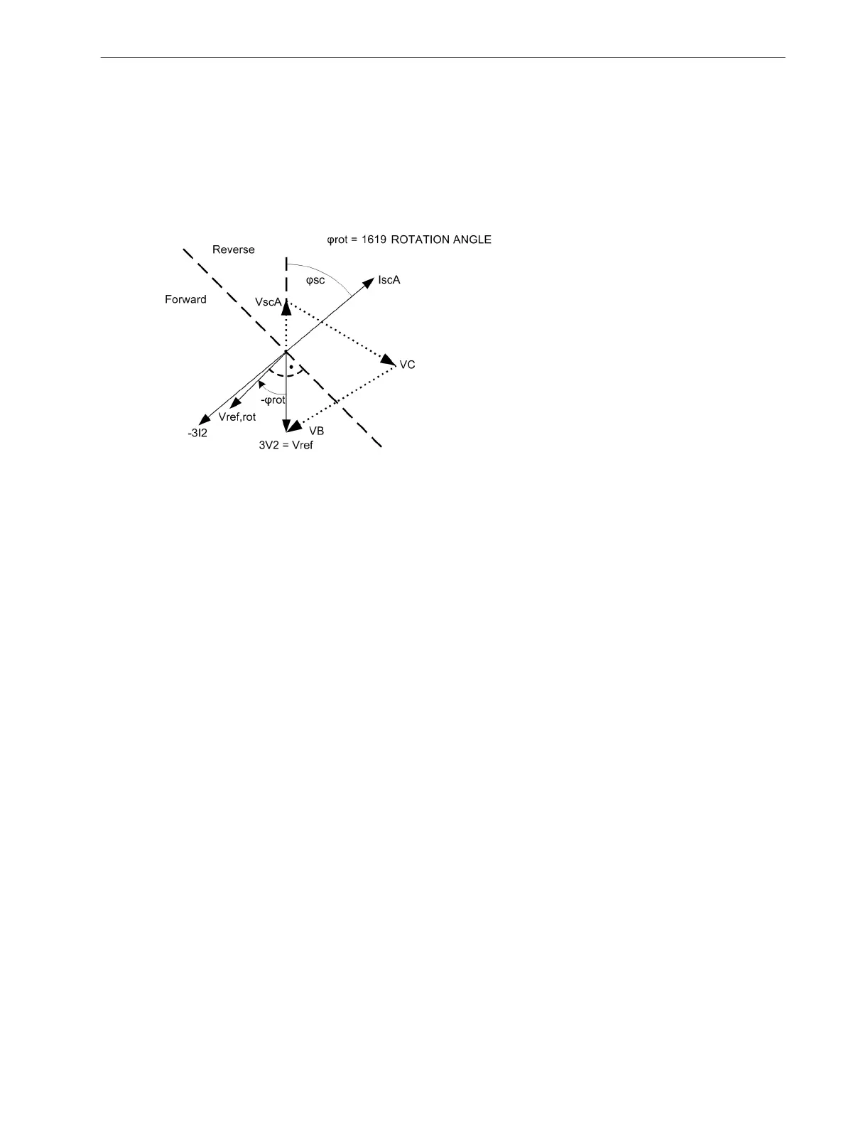
Direction Determination of Directional Ground Element with Negative Sequence Values
Figure 2-32 shows the treatment of the reference voltage for the directional ground element using the nega-
tive sequence values based on a single-phase ground fault in phase A. As reference voltage, the negative
sequence voltage is used, as current for the direction determination, the negative sequence system in which
the fault current is displayed. The fault current -3Ι
2
is in phase opposition to the fault current Ι
scA
and follows
the voltage 3V
2
by the fault angle ϕ
sc
. The reference voltage is rotated through the setting value 1619 ROTA-
TION ANGLE. In this case, a rotation of -45°.
[7sj6x_drehung-referenzspannung-erde-gegensys-220904-he, 1, en_US]
Figure 2-32 Rotation of the reference voltage, directional ground element with negative sequence values
The forward area is a range of ±86° around the rotated reference voltage V
ref, rot
. If the vector of the negative
sequence system current -3Ι
2
is in this area, the device detects forward direction.
Reverse Interlocking for Double End Fed Lines
Application Example
The directionality feature of the directional overcurrent protection enables the user to perform reverse inter-
locking also on double end fed lines using relay element 67-1. It is designed to selectively isolate a faulty line
section (e.g. sections of rings) in high speed, i.e. no long graded times will slow down the process. This
scheme is feasible when the distance between protective relays is not too great and when pilot wires are avail-
able for signal transfer via an auxiliary voltage loop.
For each line, a separate data transfer path is required to facilitate signal transmission in each direction. When
implemented in a closed-circuit connection, disturbances in the communication line are detected and
signalled with time delay. The local system requires a local interlocking bus wire similar to the one described
in Subsection "Reverse Interlocking Bus Protection" for the directional overcurrent protection (Section
2.2 Overcurrent Protection 50, 51, 50N, 51N).
During a line fault, the device that detects faults in forward (line) direction using the directional relay element
67-1 will block one of the non-directional overcurrent elements (50-1, 50-TOC) of devices in the reverse direc-
tion (at the same busbar) since they should not trip (Figure 2-33). In addition, a message is generated
regarding the fault direction. "Forward" messages are issued when the current threshold of the directional
relay element 67-1 is exceeded and directional determination is done. Subsequently, "forward" messages are
transmitted to the device located in reverse direction.
During a busbar fault, the device that detects faults in reverse (busbar) direction using the directional relay
element 67-1 will block one of the non-directional overcurrent elements (50-1, 50-TOC) of devices at the
opposite end of the same feeder. In addition, a "Reverse" message is generated and transmitted via the auxil-
iary voltage loop to the relay located at the opposite end of the line.
2.3.9
Functions
2.3 Directional Overcurrent Protection 67, 67N
SIPROTEC 4, 7SJ62/64, Manual 97
C53000-G1140-C207-8, Edition 08.2016

 Loading...


