[7sj6x-logik-broken-wire-080506-he, 1, en_US]
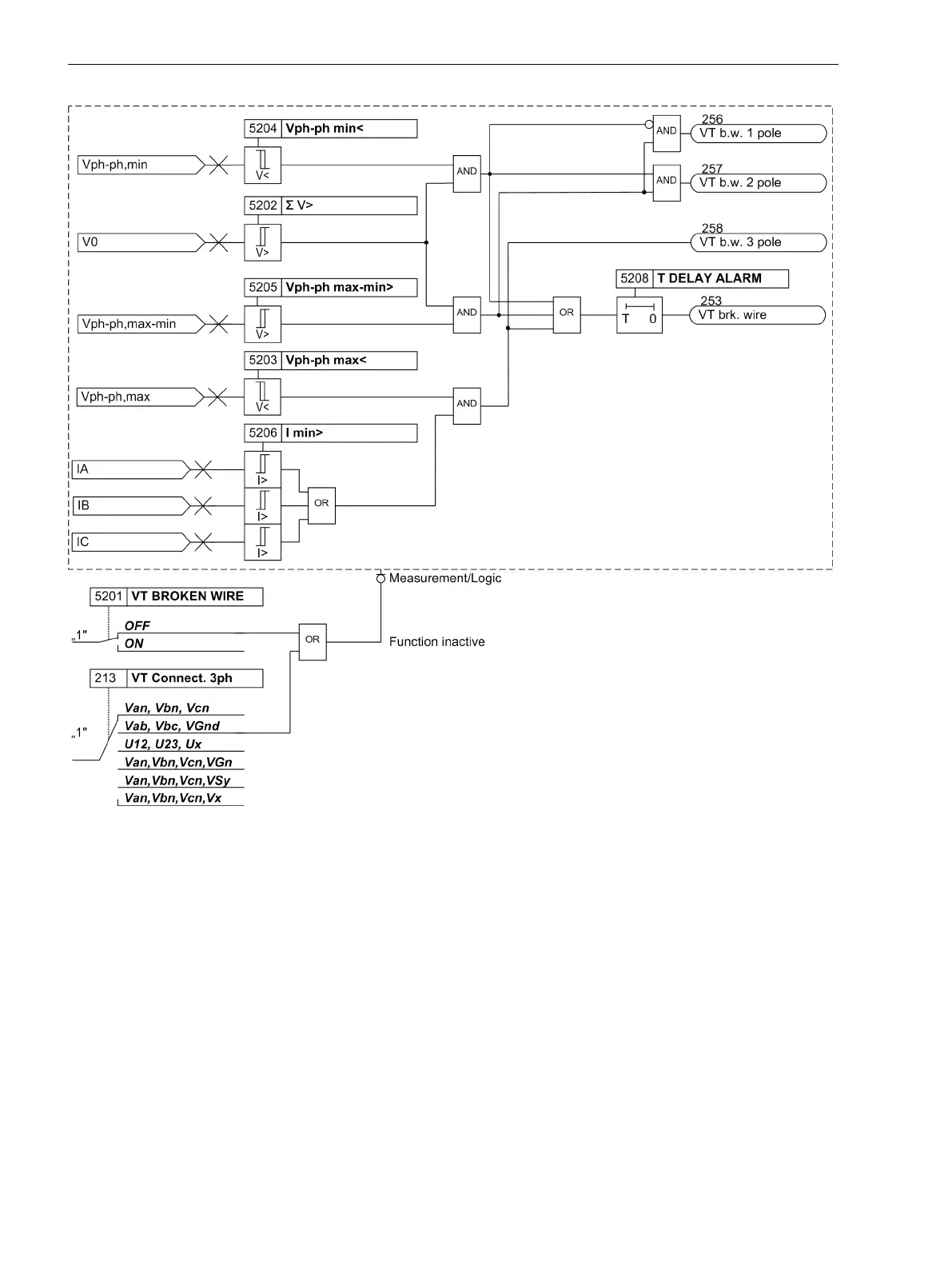
Figure 2-75
Logic diagram for broken wire monitoring
Setting Notes
Measured Value Monitoring
The sensitivity of measured value monitor can be modified. Default values which are sufficient in most cases
are preset. If especially high operating asymmetries in the currents and/or voltages are to be expected during
operation, or if it becomes apparent during operation that certain monitoring functions activate sporadically,
then the setting should be less sensitive.
Address 8102 BALANCE V-LIMIT determines the limit voltage (phase-to-phase) above which the voltage
symmetry monitor is effective. Address 8103 BAL. FACTOR V is the associated symmetry factor; that is, the
slope of the symmetry characteristic curve. In address 8110 T BAL. V LIMIT you set the delay time of fault
message no. 167
Fail V balance
.
Address 8104 BALANCE I LIMIT determines the limit current above which the current symmetry monitor is
effective. Address 8105 BAL. FACTOR I is the associated symmetry factor; that is, the slope of the
symmetry characteristic curve. In address 8111 T BAL. I LIMIT you set the delay time for fault message
no. 163
Fail I balance
.
2.12.1.8
Functions
2.12 Monitoring Functions
190 SIPROTEC 4, 7SJ62/64, Manual
C53000-G1140-C207-8, Edition 08.2016

 Loading...


