Setting Notes
General
The data for parameters 209 PHASE SEQ., 210 TMin TRIP CMD, 211 TMax CLOSE CMD and 212
BkrClosed I MIN can be entered directly at the device if it features an integrated or detached operator
panel: Press the MENU key to open the main menu. Apply the ▼ key to select SETTINGS and then press the ►
key to navigate to the SETTINGS display. To enter the Power System Data, select the P.System Data 1 in
the SETTINGS menu.
Doubleclick Parameters under DIGSI to display the relevant selection. In doing so, a dialog box with tabs will
open under P.System Data 1 where individual parameters can be configured. The following descriptions
are therefore structured according to these tabs.
Rated Frequency (Power System)
The nominal frequency of the system is set under the Address 214 Rated Frequency. The factory pre-
setting in accordance with the model need only be changed if the device will be employed for a purpose other
than that which was planned when ordering.
Phase Rotation (Power System)
Address 209 PHASE SEQ. is used to change the default phase sequence (A B C for clockwise rotation) if
your power system permanently has an anti-clockwise phase sequence (A C B. A temporary reversal of rota-
tion is also possible using binary inputs (see Section 2.23.2 Setting Notes).
Temperature Unit (Power System)
Address 276 TEMP. UNIT allows displaying the temperature values either in degrees Celsius or in degrees
Fahrenheit.
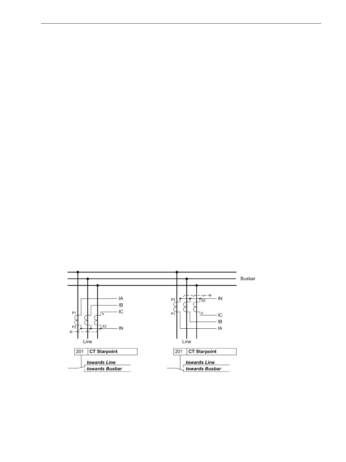
Polarity of Current Transformers (Power System)
At address 201 CT Starpoint, the polarity of the wye-connected current transformers is specified (the
following figure applies accordingly to two current transformers). This setting determines the measuring
direction of the device (forward = line direction). Changing this parameter also results in a polarity reversal of
the ground current inputs Ι
N
or Ι
NS
.
[polung-stromwandler-020313-kn, 1, en_US]
Figure 2-3 Polarity of current transformers
Current Connection Ι4 (Power System)
Here, it is communicated to the device whether the ground current of the current transformer neutral point is
connected to the fourth current input (Ι
4
). This corresponds to the Holmgreen connection, (see connection
example in C Connection Examples). In this case, parameter 280 Holmgr. for Σi is set to YES. In all other
2.1.3.2
Functions
2.1 General
SIPROTEC 4, 7SJ62/64, Manual 41
C53000-G1140-C207-8, Edition 08.2016

 Loading...


