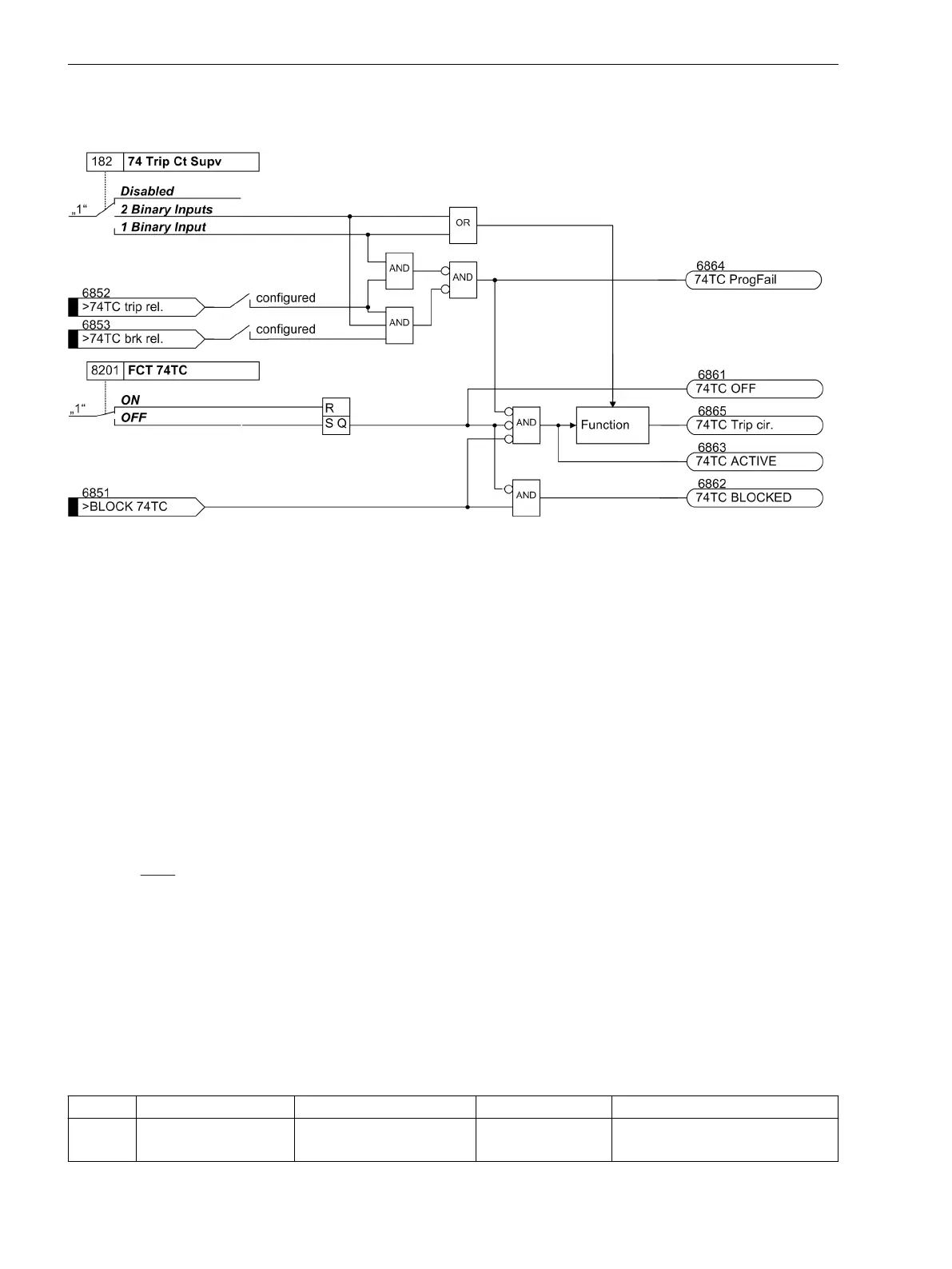
The following figure shows the logic diagram for the message that can be generated by the trip circuit
monitor, depending on the control settings and binary inputs.
[7sj6x_ausloesekreis_meldelogik-150502-kn, 1, en_US]
Figure 2-80 Message logic for trip circuit supervision
Setting Notes
General
The function is only effective and accessible if address 182 (Section 2.1.1.2 Setting Notes) was set to either 2
Binary Inputs or 1 Binary Input during configuration, the appropriate number of binary inputs has
been configured accordingly for this purpose and the function FCT 74TC is ON at address 8201. If the alloca-
tion of the required binary inputs does not match the selected supervision type, a message to this effect is
generated (
74TC ProgFail
). If the trip circuit monitor is not to be used at all, then Disabled is set at
address 182.
In order to ensure that the longest possible duration of a trip command can be reliably bridged, and an indica-
tion is generated in case of an actual fault in the trip circuit, the indication regarding a trip circuit interruption
is delayed. The time delay is set under address 8202 Alarm Delay.
Supervision with One Binary Input
Note: When using only one binary input (BI) for the trip circuit monitor, malfunctions, such as interruption of
the trip circuit or loss of battery voltage are detected in general, but trip circuit failures while a trip command
is active cannot be detected. Therefore, the measurement must take place over a period of time that bridges
the longest possible duration of a closed trip contact. This is ensured by the fixed number of measurement
repetitions and the time between the state checks.
When using only one binary input, a resistor R is inserted into the circuit on the system side, instead of the
missing second binary input. Through appropriate sizing of the resistor and depending on the system condi-
tions, a lower control voltage is mostly sufficient.
Information for dimensioning resistor R is given in the Chapter "Installation and Commissioning" under Config-
uration Notes in the Section "Trip Circuit Supervision".
Settings
Addr.
Parameter Setting Options Default Setting Comments
8201 FCT 74TC ON
OFF
ON 74TC TRIP Circuit Supervision
2.12.2.2
2.12.2.3
Functions
2.12 Monitoring Functions
196 SIPROTEC 4, 7SJ62/64, Manual
C53000-G1140-C207-8, Edition 08.2016

 Loading...


