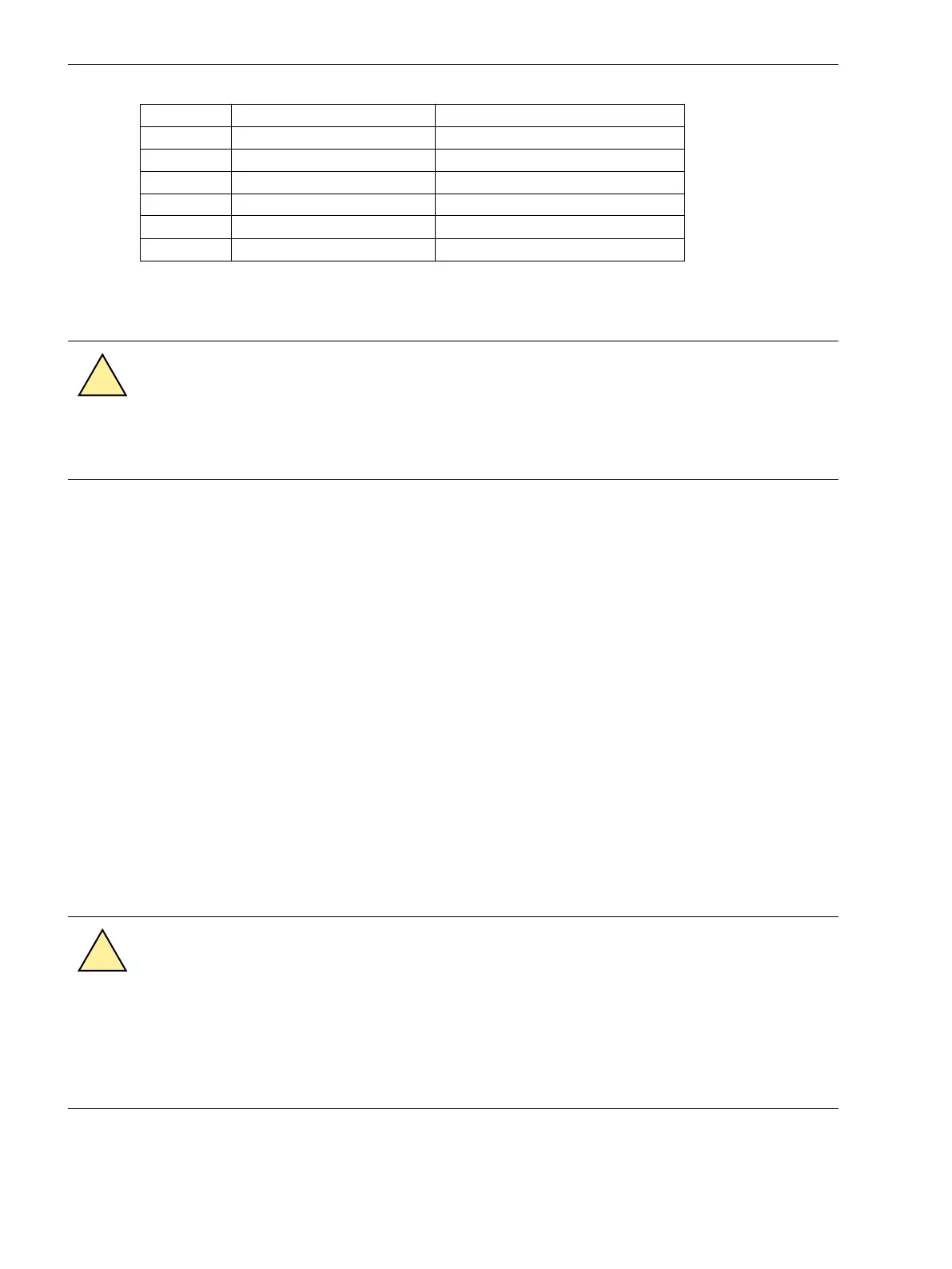
Pin-No. Description Signal Meaning
4
–
1)
–
1)
5 SHIELD Shield Potential
6 – –
7 P12_TSIG Input 12 V
8
P_TSYNC
1)
Input 24 V
1)
9 SHIELD Shield Potential
1)
assigned, but not used
Fiber-optic Cables
WARNING
Laser Radiation!
²
Do not look directly into the fiber-optic elements!
Signals transmitted via optical fibers are unaffected by interference. The fibers guarantee electrical isolation
between the connections. Transmit and receive connections are represented by symbols.
The standard setting of the character idle state for the optical fiber interface is “Light off”. If the character idle
state is to be changed, use the operating program DIGSI as described in the SIPROTEC 4 System Description.
RTD-Box (Resistance Temperature Detector)
If a 7XV566 RTD-Box is connected, check the connections to the interface (Port C or D).
Verify also the termination: The terminating resistors must be connected to 7SJ62/64 (see margin heading
“Termination”).
For more information on the 7XV5662-6AD10, please refer to the enclosed device manual. Check the trans-
mission parameters at the RTD box. In addition to the baud rate and the parity, the bus number is important,
too.
When connecting a 7XV5662-6AD10 RTD box, set the following bus numbers at the RTD box:
•
Bus number = 1 for RTD 1 to 6
•
Bus number = 2 for RTD 7 to 12.
Please observe that sensor input 1 (RTD1) of the RTD box is reserved for input of the ambient temperature or
coolant temperature of the overload protection.
Checking the System Connections
WARNING
Warning of dangerous voltages
Non-observance of the following measures can result in death, personal injury or substantial prop-
erty damage.
²
Therefore, only qualified people who are familiar with and adhere to the safety procedures and
precautionary measures should perform the inspection steps.
3.2.2
Mounting and Commissioning
3.2 Checking Connections
414 SIPROTEC 4, 7SJ62/64, Manual
C53000-G1140-C207-8, Edition 08.2016

 Loading...


