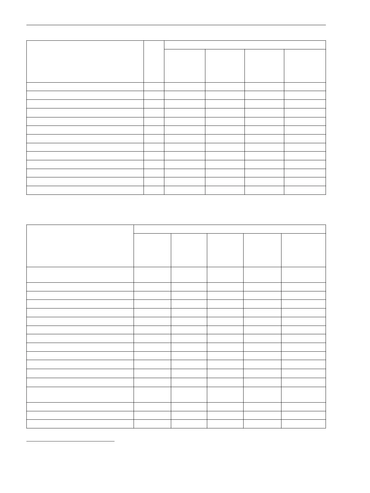
Function
Function Points
Default Setting in the Application Template
Template 1
Template 2
Template 3
Template 4
Binary input – 1 1 1 1
Binary output – 1 1 1 1
Communication channel – 1 1 1 1
Process monitor
1
– 1 1 1 1
Function key – 1 1 1 1
GOOSE input – 0 0 0 0
LED, multicolor – 1 1 1 1
Measuring Transducers – 0 0 0 0
CFC standard – 0 0 0 0
CFC arithmetic 40 0 0 0 0
CFC logic – 1 1 1 1
CFC timer – 0 0 0 0
CFC switching sequences – 0 0 0 0
The following table shows the maximum quantity structure of the fault recorder.
Table 4-2 Maximum Possible Quantity Structures
Function Significant Feature
8 Channels
16 Channels
24 Channels
32 Channels
40 Channels
Hardware quantity structure expandable
(I/O)
1 1 1 1 1
FG Voltage (FG V) 2 4 6 8 10
FG Voltage/Current (FG VI) 2 4 6 8 10
FG ComModule 5 5 5 5 5
FG Recording 1 1 1 1 1
FG Simulation 1 1 1 1 1
FG Analog units 1 1 1 1 1
Phasor Measurement Unit (PMU) 2 2 2 2 2
Power-system data (power system) 1 1 1 1 1
Fast-scan recorder 1 1 1 1 1
Slow-scan recorder
2 2 2 2 2
Continuous recorder
5 5 5 5 5
Trend recorder
2 2 2 2 2
Measured values, extended: Min, max,
average
9 9 9 9 9
Voltage trigger 2 4 6 8 10
Current trigger 2 4 6 8 10
Frequency trigger 2 4 6 8 10
1
The process monitor provides background information such as current-flow criterion and closure detection. The user can neither set
parameters for, nor delete, this function.
Applications
4.2 Application Template and Functional Scope for the Fault Recorder
106 SIPROTEC 5, Fault Recorder, Manual
C53000-G5040-C018-5, Edition 11.2017

 Loading...


