These modules are then freely assignable to ports E, F, N, or P of the device, see Figure 6-17. You can view the
selected port in the (_:10621:104) Port. This parameter is automatically managed by DIGSI and cannot
be changed.
[sccommod-140213-01.tif, 1, en_US]
Figure 6-17 Placement of Communication Modules
NOTE
Port M of the CB202 plug-in module assembly is used to accommodate measuring-transducer modules and
cannot be used for the installation of communication modules.
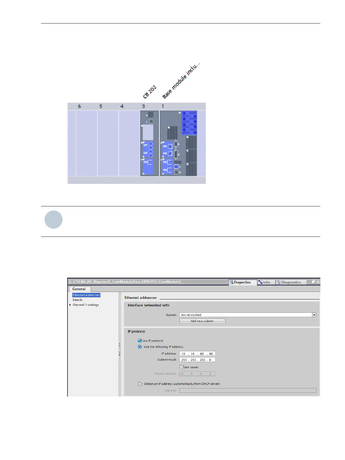
Addressing
You must configure the respective Ethernet address (IP address, subnet mask, etc.) for each communication
module in DIGSI. This is done in the DIGSI General settings properties dialog of the communication module in
item Ethernet addresses and so forms the IP address for the respective PMU.
[scethern-210415, 1, en_US]
Figure 6-18 Ethernet Address Configuration
In the DIGSI properties dialog for channel 1, select the synchrophasor protocol, see the following figure.
Function-Group Types
6.4 Function-Group Type Phasor Measurement Unit (PMU)
SIPROTEC 5, Fault Recorder, Manual 159
C53000-G5040-C018-5, Edition 11.2017

 Loading...


