[scaddios-140213-01.tif, 1, en_US]
Figure 6-22 Adding Additional Input/Output Modules
[scroutin-210415, 1, en_US]
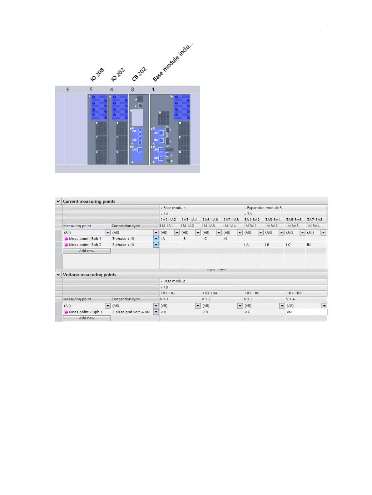
Figure 6-23 Assignment of the Current and Voltage Inputs of the Added Input/Output Modules on Meas-
uring Points
The maximum numbers of measuring points that can be routed for one PMU are:
•
2 x 3-phase voltage measuring points
•
2 x 3-phase current measuring points
•
2 x 1-phase voltage measuring points
•
2 x 1-phase current measuring points
You can assign all supported measuring points to any PMU, see the following figure. However, each PMU must
be connected to a 3-phase voltage measuring point.
Function-Group Types
6.4 Function-Group Type Phasor Measurement Unit (PMU)
164 SIPROTEC 5, Fault Recorder, Manual
C53000-G5040-C018-5, Edition 11.2017

 Loading...


