[scfgconn-210415, 1, en_US]
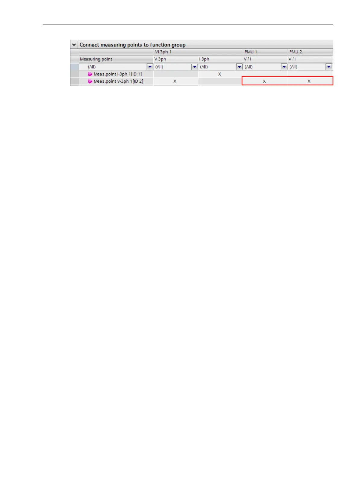
Figure 6-24 Connecting Measuring Points to the Configured PMU Function Groups
When these setting steps have been completed, the PMUs are fully configured. The PMU is a function group
that functions independently of all the other function groups instantiated in the device.
The device load, however, is dependent on:
•
Number of PMUs
•
Performance class (where Class M generates the greater load)
•
Number of assigned channels
•
Configured reporting rate of each PMU
•
Number of binary signals to be transferred
Changing the Channel Names of Phasors
You can edit the names of the individual phasor channels for voltage and current in DIGSI. The clearly struc-
tured channel designations assist with when testing and commissioning PMU systems. Furthermore, only the
names visible in the IEEE C37.118 interface can be changed. The function block designations themselves
cannot.
The IEEE C37.118 defines the ASCII character set for changing the channel names in the scope of the
SIPROTEC 5-PMU support. Due to the protocol, the designation length is limited to 16 ASCII characters per
channel. However, when renaming, you have to assign at least 1 character. The renaming of binary channels
is not supported in the current implementation.
You can start the renaming by setting the check mark at Own phasor names with the parameterization in
the PMU function block Functional settings. Once you have activated this check mark, define a separate
name for each phasor. For this purpose, DIGSI shows all routed measuring points on the PMU in the function
group connections (see following figure).
Function-Group Types
6.4 Function-Group Type Phasor Measurement Unit (PMU)
SIPROTEC 5, Fault Recorder, Manual 165
C53000-G5040-C018-5, Edition 11.2017

 Loading...


