(1) If the setting Range active is set to test , the setting Transformation ratio is not
displayed.
(2) If the setting Range active is set to false, the settings Upper limit, Transformation
ratio upper limit, Lower limit and Transformation ratio are not displayed.
Measured-Value Calculation
The function 20-mA channel processes a single 20-mA current signal supplied by the 20-mA unit of the corre-
sponding channel. The 20-mA current measured value is converted into the correct physical quantities such as
temperature or pressure. In each 20-mA functional unit (Ether. and serial) there are always 12 of the 20-mA
channel function blocks, even if fewer channels are connected with the 20-mA unit. The calculated values are
available for further processing via CFC, GOOSE, protocols, and the display image.
Measured-Value Processing
The 20-mA unit typically transmits a value which represents a physical quantity, such as a temperature or a
pressure. Therefore, the device must contain a characteristic curve that maps the physical quantity to the 20-
mA value. If you do not activate the Range active setting (no x in the check box), the function operates
over the range 0 mA to 20 mA. If a value smaller than 0 mA or greater than 20 mA is active at the input of the
20-mA unit, the measured value is identified as invalid. The setting of the range for the scaled value goes from
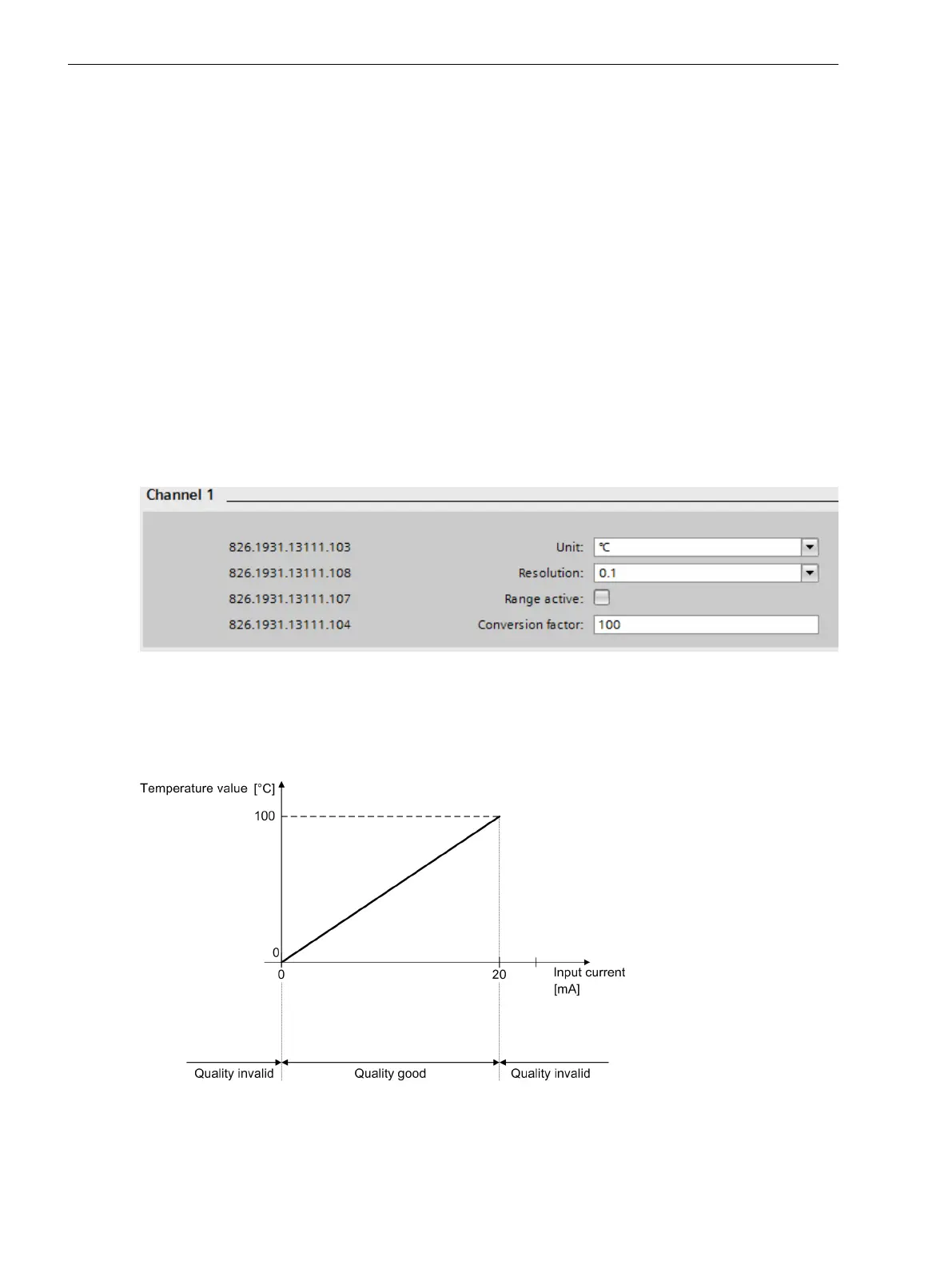
a usable range of 0 mA to 20 mA. The following figure shows an example.
[sckanumw-190214-01, 1, en_US]
Figure 6-36 Settings for Example 1
In this example, the measured value 0 mA means a temperature of 0 °C and the measured value 20 mA means
a temperature of 100 °C. So enter as Unit = °C and Conversion factor = 100. The resolution (decimal
place) of the temperature value can be chosen; for a decimal place, select Resolution = 0.1.
[dwknges3-020513-01.tif, 1, en_US]
Figure 6-37 Characteristic Curve of a 20-mA Input (Example 1)
Function-Group Types
6.5 Function-Group Type Analog Units
176 SIPROTEC 5, Fault Recorder, Manual
C53000-G5040-C018-5, Edition 11.2017

 Loading...


