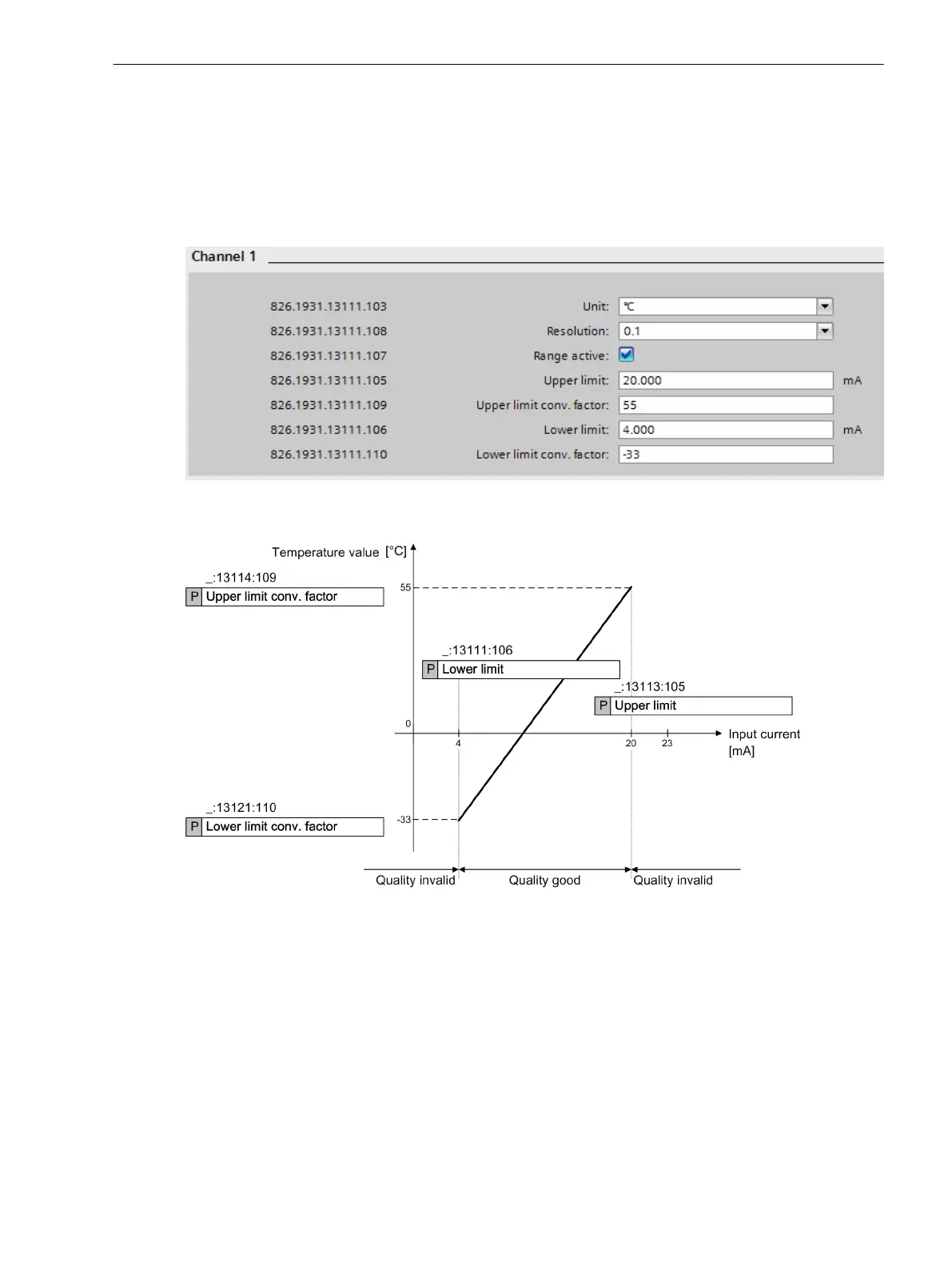
If you activate the Range active setting, then 4 additional parameters Upper limit, Lower limit,
Upper limit - Sensor, and Lower limit - Sensor appear. The parameters Upper limit and
Lower limit indicate the range of the input current in mA. The setting Upper limit - Sensor is the
calculated measured value if the input current corresponds to the value in the Upper limit setting. The
setting Lower limit - Sensor is the calculated measured value if the input current corresponds to the
value in the Lower limit setting. The setting of the range for the scaled value corresponds to the useable
range between Lower limit and Upper limit (see following figure).
[sckanumf-190214-01, 1, en_US]
Figure 6-38 Settings for Example 2
[dwknges2-020513-01.tif, 1, en_US]
Figure 6-39 Characteristic Curve of a 20-mA Unit (Example 2)
In this example, the Range active setting is selected. The setting Upper limit is at 20 mA, the setting
Lower limit is at 4 mA. The setting Upper limit - Sensor is at 55 and the setting Lower limit -
Sensor is at -33. If the input current is smaller than 4 mA or greater than 20 mA, the quality of the scaled
measured value in this example is invalid.
Each 20-mA channel makes available the scaled measured value in the information routing (these are the
temperature values in the examples) and the original current measured value in mA for further processing.
The 20-mA values can be displayed in the display page and processed with CFC charts.
Error Responses
If the current input value is determined to be incorrect, the quality attribute of the output value is set to
invalid
That status for
Health
and the defect status assume the states displayed in the table.
Function-Group Types
6.5 Function-Group Type Analog Units
SIPROTEC 5, Fault Recorder, Manual 177
C53000-G5040-C018-5, Edition 11.2017

 Loading...


