EasyManuals Logo

Siemens SIPROTEC 5 User Manual

Siemens SIPROTEC 5
490 pages
To Next Page IconTo Next Page
To Previous Page IconTo Previous Page
Page #218 background imageLoading...
Page #218 background image
[dwflussr-161012-01.tif, 1, en_US]
Figure 7-5 Signal Flow Direction in the Fault Recorder
In the following are the most important steps for setting the parameters for your fault recorder. A detailed
description of DIGSI 5 options can be found in the DIGSI Help.
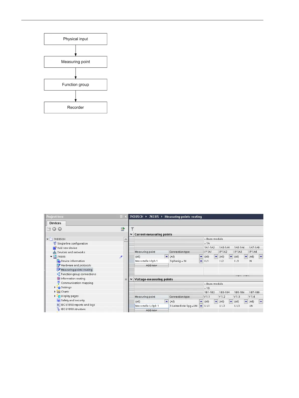
Routing Measuring Points
You can use the Measuring-point routing matrix to route the physical inputs of a inputs of the SIPROTEC 5
device to the inputs of current and voltage measuring points.
²
Double-click Measuring point routing.
²
Finally, click Add. A window for selecting the phase characteristic (3-phase or 1-phase) appears.
²
Select both for the current and the voltage measuring points either the 3-phase or 1-phase characteristic.
²
Select the connection type.
²
Route the phases on the measuring points.
[scmes7ke-180213-01.tif, 1, en_US]
Figure 7-6 Route Measuring Points
Detailed information on the clamp designations, for example 1A, is in the Hardware Manual and in the hard-
ware configuration.
In addition you can use the Current measuring points and Voltage measuring points window to add other
measuring points to the application.
Fault Recorder
7.1 Introduction to DIGSI 5
218 SIPROTEC 5, Fault Recorder, Manual
C53000-G5040-C018-5, Edition 11.2017

Table of Contents

Other manuals for Siemens SIPROTEC 5

Questions and Answers:

Question and Answer IconNeed help?

Do you have a question about the Siemens SIPROTEC 5 and is the answer not in the manual?

Siemens SIPROTEC 5 Specifications

General IconGeneral
SeriesSIPROTEC 5
Communication ProtocolsIEC 61850, DNP3, Modbus
CybersecurityRole-based access control, secure communication
Modular DesignYes
Hardware RedundancyOptional
Operating Temperature-25°C to +70°C
Digital InputsConfigurable, number depends on I/O modules
Digital OutputsConfigurable, number depends on I/O modules
Analog InputsConfigurable, number depends on I/O modules
Current Transformer InputsConfigurable, number depends on I/O modules
Voltage Transformer InputsConfigurable, number depends on I/O modules
Time SynchronizationIRIG-B, SNTP, PTP
Protection FunctionsOvercurrent, Differential, Distance, Over/Under Voltage, Frequency
Housing19-inch Rack Mount
DimensionsDepends on module configuration
WeightDepends on module configuration
Voltage Input24V DC, 48V DC, 110V DC, 125V DC, 220V DC, 250V DC

Related product manuals