EasyManuals Logo

Siemens SIPROTEC 5 User Manual

Siemens SIPROTEC 5
490 pages
To Next Page IconTo Next Page
To Previous Page IconTo Previous Page
Page #258 background imageLoading...
Page #258 background image
[dwtrigwi-140213-01.tif, 1, en_US]
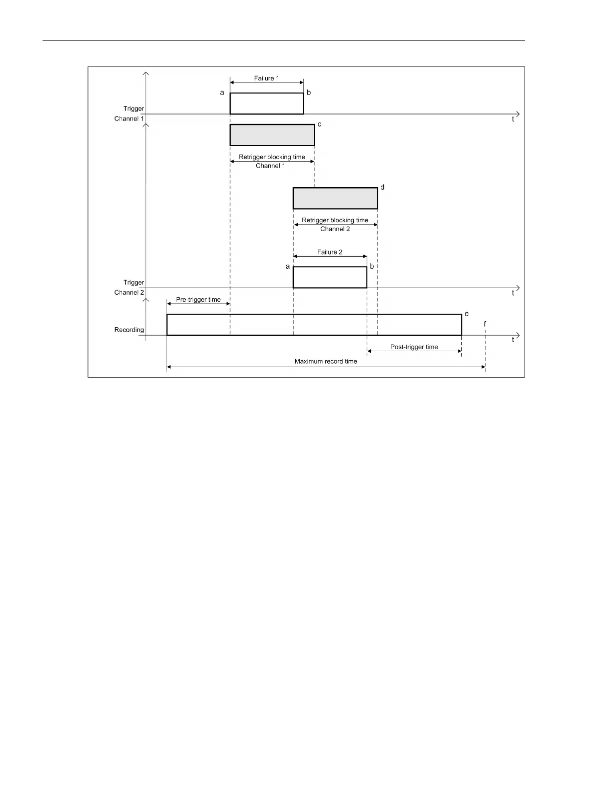
Figure 7-40
Example 2: Triggers in 2 Channels
a Trigger rising edge: Start of the recording of the pre-trigger time and the retrigger blocking time,
as well as with the 1st trigger event start of the maximum record time
b Trigger falling edge
c End of the retrigger blocking time, channel 1
d End of the retrigger blocking time, channel 2
e End of the post-trigger time
f End of the maximum record time
t Time line
When a trigger event occurs, the start trigger (a) trips a fault record. Another limit violation of the second
channel occurs within the retrigger blocking time of the first channel (c). This extends the fault record (e)
because the retrigger block acts only on the appropriate channel.
Each individual channel can trip a retrigger. The retrigger blocking time can be activated separately for each
analog input.
Retrigger Blocking Time with Trigger Reason
Each threshold (Max. trigger, Min. trigger, dM/dt rise (/Filter time) or dM/dt drop (/
Filter time)) of a channel has its own retrigger blocking time. That is, for example, one Min. trigger
can extend the recording started by the Max. trigger once (see the figure below).
Fault Recorder
7.2 Function-Group Type Recorder
258 SIPROTEC 5, Fault Recorder, Manual
C53000-G5040-C018-5, Edition 11.2017

Table of Contents

Other manuals for Siemens SIPROTEC 5

Questions and Answers:

Question and Answer IconNeed help?

Do you have a question about the Siemens SIPROTEC 5 and is the answer not in the manual?

Siemens SIPROTEC 5 Specifications

General IconGeneral
SeriesSIPROTEC 5
Communication ProtocolsIEC 61850, DNP3, Modbus
CybersecurityRole-based access control, secure communication
Modular DesignYes
Hardware RedundancyOptional
Operating Temperature-25°C to +70°C
Digital InputsConfigurable, number depends on I/O modules
Digital OutputsConfigurable, number depends on I/O modules
Analog InputsConfigurable, number depends on I/O modules
Current Transformer InputsConfigurable, number depends on I/O modules
Voltage Transformer InputsConfigurable, number depends on I/O modules
Time SynchronizationIRIG-B, SNTP, PTP
Protection FunctionsOvercurrent, Differential, Distance, Over/Under Voltage, Frequency
Housing19-inch Rack Mount
DimensionsDepends on module configuration
WeightDepends on module configuration
Voltage Input24V DC, 48V DC, 110V DC, 125V DC, 220V DC, 250V DC

Related product manuals