Identifying the Measuring Points
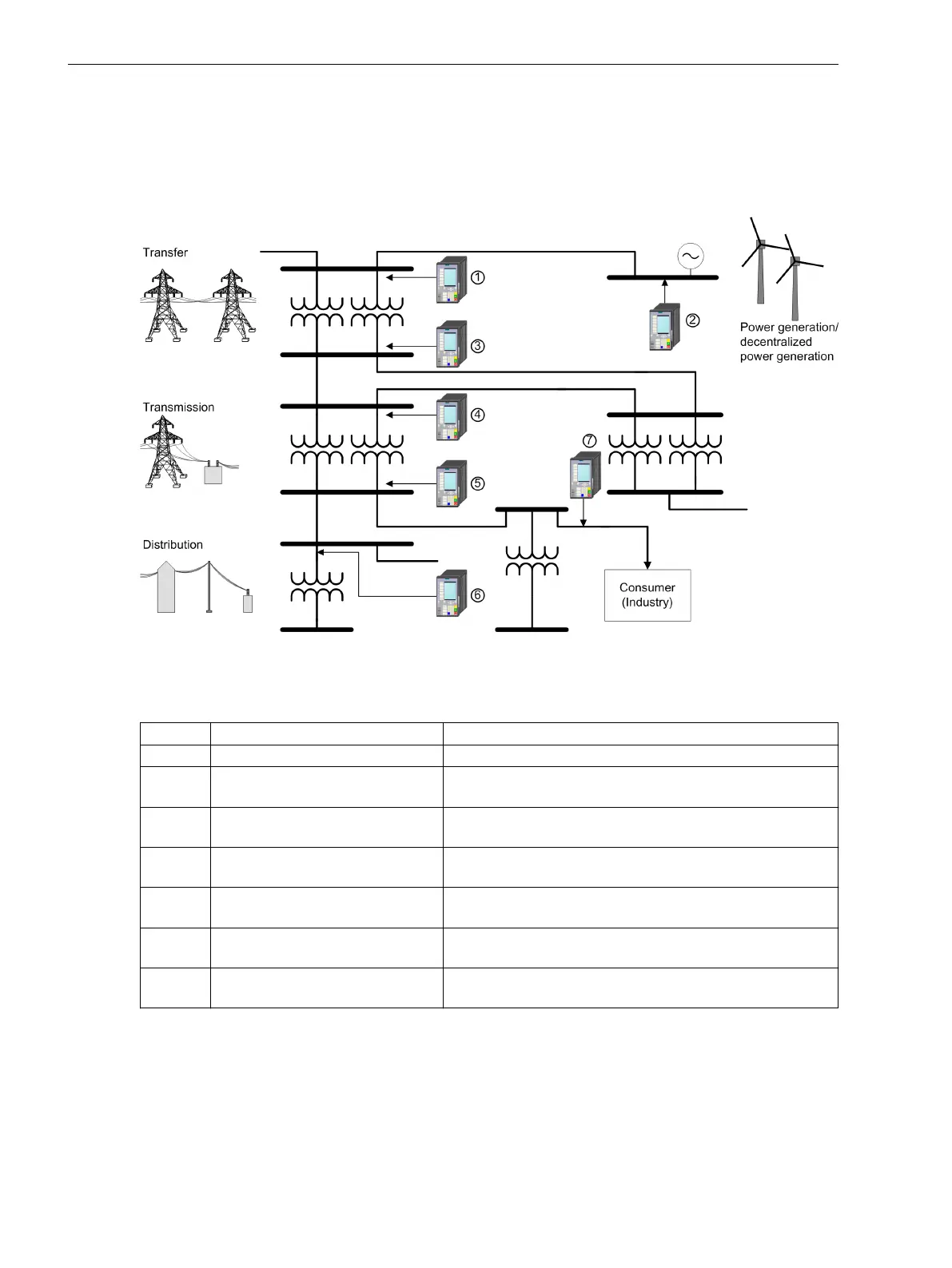
The measuring points can be assigned and established for example as in the Figure 1-3. The fault record or PQ
data acquisition requires, in addition to the selection of the measuring point, also a definition and establish-
ment of the evaluation criteria at the individual measuring points. There the monitoring of the Network
Quality is a combination of data acquisition techniques, which are classified according to purpose or use.
[dwnetzve-161012-01.tif, 1, en_US]
Figure 1-3
General Display of the Measuring Points
Table 1-1 Assignment of measuring points
No. Measuring Points Location
1 Infeed (line or transformer) Possible busbars
2 Power generation/decentral power
generation
Busbars, transformers or generator connection
3 Forwarding, distribution system Busbars (for example, if the busbar belongs to the transmis-
sion company and is run by it.)
4 Forwarding, infeed (line or trans-
former)
Decentral line connection (for example, if the line belongs to
the transmission company and is run by it.)
5 Forwarding, distribution system Transformer secondary circuit or cable for adjacent trans-
former station
6 Distribution, infeed (line or trans-
former)
Distribution transformer
7 Power distribution, consumers Distribution transformers (for example, if the transformer
belongs to the transmission company and is run by it.)
Introduction
1.5 Scope of Functions
30 SIPROTEC 5, Fault Recorder, Manual
C53000-G5040-C018-5, Edition 11.2017

 Loading...


