The following setting example shows how you can change the transformer ratio in DIGSI 5, and what impact
this has on the settings in the setting views Primary and Secondary. The setting is seen in the example of the
3-phase voltage/current function.
The following output data are assumed:
Voltage transformer: 400 kV/100 V
Threshold value dM/dt falling: 20 V
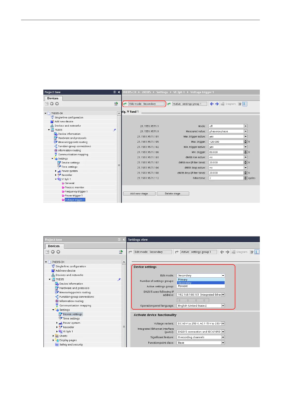
The following figure shows the setting of the trigger function Trig. V Fund. in the secondary view. The
threshold value of the stage is set to 20 V.
[sc7kemod-280113-01.tif, 1, en_US]
Figure 3-42 Trigger Setting, Display of the Active Setting Sheet
When you click the green arrow in the setting sheet at the upper left, you get to the window for switching
over to the setting view (see the following figure). Select the setting view you prefer.
[sc7keger-280113-01.tif, 1, en_US]
Figure 3-43 Switchover to the Desired Setting View
System Functions
3.7 General Notes for Setting the Threshold Value of Trigger Functions
96 SIPROTEC 5, Fault Recorder, Manual
C53000-G5040-C018-5, Edition 11.2017

 Loading...


