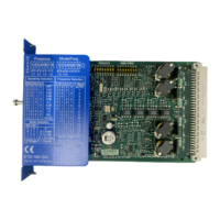
Overview
3.2 A typical system configuration
Modular Safety System 3RK3
22 System Manual, 10/2008, 926 2530-02 DS 02
3.2 A typical system configuration
The schematic diagram below shows a typical MSS configuration. The system comprises a
central unit, expansion modules, an interface module and a diagnostics module.
;;
'(9,&(
6)
5.%$
066'3,QWHUIDFH
352),%86'3
/0)(
%)
7,1,1,1,1
7,1,1,1,1
444/0)(
;;
'(9,&(
6)
5(6(7
,1,1,1,14
,1,1,1,14
5.$$
066%DVLF
6),1,14
,1,14
7,1,1
7,1,1
/04
444
5.$$
)',)52
6),1,14
,1,14
7,1,1
7,1,1
/0
44
5.$$
)',)'2
4)444
4444
444
444
/00
440
5.$$
'2
6),1,1,1,1
,1,1,1,1
7,1,1
7,1,1
/0,1
,1,1,1
5.$$
)',
SIRIUS 3RK3
DEVICE
BF
SF
(1) Diagnostics module
(2) Interface module
(3) Central unit
(4) ... (7) Expansion modules (max. 7 expansion modules)
(8) Memory module
Figure 3-1 A typical system configuration with MSS

 Loading...


