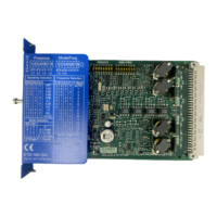
Description of the hardware
5.1 Description of the individual modules
Modular Safety System 3RK3
44 System Manual, 10/2008, 926 2530-02 DS 02
Interfaces of the 3RK3 Basic central unit
Interface Meaning Description
X1 System interface Connection of PC / PG, interface module
X2 Interface Interface for connecting expansion modules (e.g. I/O
modules)
X3 External memory module Slot for external memory module with parameterization
data
Operator controls on the 3RK3 Basic central unit
Element Meaning Description
RESET
button
Error acknowledgement
Factory settings
Confirm the acknowledgeable errors with this button.
Please note the paragraph about factory settings.
Displays of the 3RK3 Basic central unit
Element Meaning
DEVICE Status
SF Group error
IN1 ... IN8 Sensor inputs
Q1, Q2 Safety-related outputs
Connecting inputs and outputs
You can find more information on connecting inputs and outputs in the section Connecting
safety-related inputs and outputs (Page
69).

 Loading...


