Description of the hardware
5.1 Description of the individual modules
Modular Safety System 3RK3
48 System Manual, 10/2008, 926 2530-02 DS 02
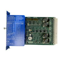
Design of the expansion module 2/4F-DI 1/2F-RO
Front view No. Meaning
(1) Removable terminal block D
(2) Removable terminal block C
(3) Interface X2
(4) Inscription label
(5) Removable terminal block A
(6) Removable terminal block B
(7) Display LEDs
,1),14
,1,14
7,1,1
7,1,1
/04
444
5.$$
)',)52
(8) Interface X1
Terminal designations of the expansion module 2/4F-DI 1/2F-RO
Terminal Meaning Description
T1 Test output for inputs IN1,
IN3
T2 Test output for inputs IN2,
IN4
Test outputs with different test signals
Connection for sensor contacts for detecting cross-
circuits
IN1 ... IN4 Safety-related sensor inputs Connection for safety sensors
Combinations for two-channel connection method:
IN1-IN2, IN3-IN4
Q1.1, Q1.2 Safety-related relay output
Q2.1, Q2.2 Safety-related relay output
Isolated output for connecting actuators
L+ Power supply 24 V DC
M Ground Ground to 24 V DC
Interfaces of the expansion module 2/4F-DI 1/2F-RO
Interface Meaning Description
X1 Interface Connection of central unit/expansion module
X2 Interface Connection of expansion module

 Loading...


