Mounting / connection
4.1 Mounting
M200D PROFIBUS/PROFINET
Manual, 08/2014, A5E01577426A/RS-AA/004
101
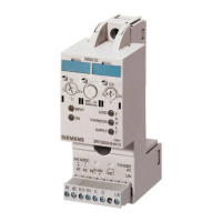
Setting the PROFIBUS DP address at the communication module and activating the terminating
resistor
1. Remove the screw cap from the communication module.
2. Set the PROFIBUS DP address using the DIP switches (see the example).
3. If the PROFIBUS DP is the last node on this system, enable the terminating resistor using
the DIP switch.
4. Turn the cap on the communication module again (torque: 1 Nm to 1.5 Nm).
If the terminating resistor is enabled, PROFIBUS DP is terminated.
Enabling and disabling the terminating resistor
Setting PROFIBUS DP address 1 to 125
Figure 4-6 Setting the PROFIBUS DP address and the terminating resistor
The following PROFIBUS DP address is set on the DIP switch: 1 + 4 + 16 + 64 = 85
ON OFF ON OFF ON OFF ON
Any modification of the PROFIBUS DP address is not validated unless you cycle the
electronic/encoder power supply off and on.
If the invalid address 127 is set using the DIP switch, the motor starter signals "Group fault"
and "Invalid parameter value".
Please set a valid address (1 to 125) to acknoweldge the error!

 Loading...