Functions
3.5 Motor control
M200D PROFIBUS/PROFINET
38 Manual, 08/2014, A5E01577426A/RS-AA/004
A motor-mounted mechanical disk or spring-loaded brake is used to brake the motor. The
brake is controlled via the brake output.
M200D motor starters offer the possibility of switching the brake of a motor separately via an
internal electronic output (order variant). This electronic output can be controlled via the
process image of the motor starter independently of the switching status of the
contactors/thyristors and thus of the motor status.
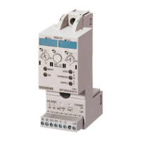
The following circuit diagram illustrates the mechanical braking procedure with a 180 V DC
brake output:
1 Phase L1
2 -
3 Phase L3
4 Brake L1 (switched)
5 Thermistor
6 Brake L3 (direct)
7 Phase L2
8 Thermistor
PE (yellow/green)

 Loading...