Mounting / connection
4.2 Connection
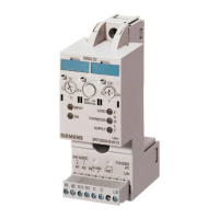
M200D PROFIBUS/PROFINET
Manual, 08/2014, A5E01577426A/RS-AA/004
103
Required components/cables
Selecting the power cables
Hazardous Voltage
Can Cause Death, Serious Injury, or Property Damage
Before starting work, disconnect the system and devices from the power supply.
The cross-section of the power cables must be suitable for the prevailing ambient conditions.
The following factors determine the cross-section:
● The current set on the device
● The cable installation type
● The ambient temperature
● The type of material (PVC, rubber)
The following maximum current-carrying capacities apply for PVC power cables when
installed, for example, in the cable duct (depending on the ambient temperature):
1.5 mm
2
14 A 12.2 A 11.1 A 9.9 A 8.5 A
2.5 mm
2
19 A 16.5 A 15.0 A 13.5 A 11.6 A
4.0 mm
2
26 A 22.6 A 20.5 A 18.5 A 15.9 A
6.0 mm
2
33 A 28.7 A 26.1 A 23.4 A 18.2 A
Seal unused connections with sealing caps since this is the only way to ensure degree of
protection IP65. The sealing caps of the digital inputs and outputs are mounted on the motor
starter module as delivered.
The sealing caps are also available as accessories:
Sealing cap M12 10 pieces 3RK1901-1KA00
Sealing cap 7/8" 10 pieces 6ES7194-3JA00-0AA0

 Loading...