General Operation
7.11 Open Channel Monitoring (OCM)
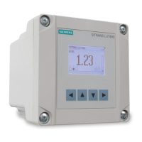
SITRANS LUT400
Operating Instructions, 07/2019, A5E33329501-AC
123
7.11.3 Setting Zero Head
Many PMDs start flowing higher than the traditional empty distance of the application. You
can account for the flow in one of two ways:
1. Use Zero Head Offset (2.15.3.5.) (Page 233) to have OCM calculations ignore levels
below that value. Possible head = Low Calibration Point (2.2.1.) (Page 171) minus High
Calibration Point (2.2.2.) (Page 172).
Note
Maximum Head (2.15.3.3.)
(Page 232) is preset to Low Calibration Point (2.2.1.)
171) minus High Calibration Point (2.2.2.) (Page 172) and is not updated when
Zero Head Offset (2.15.3.5.)
(Page 233) is used. Make sure you set Maximum Head
(Page 232) to the correct value when using Zero Head Offset (2.15.3.5.)
233). (Refer to PMD supplier documentation for Maximum Head.).
2. Use Far Range (2.2.5.) (Page 172) where the empty level is set to the bottom of the weir,
and above the bottom of the channel. It should be used if the surface monitored can fall
past the Low Calibration Point (2.2.1.) (Page 171) level in normal operation without
reporting an LOE. The value is added to Low Calibration Point (2.2.1.) (Page 171) and
can be greater than the range of the transducer.
The examples on the following pages show both methods.
 Loading...