Installing and Mounting
4.2 Mounting instructions
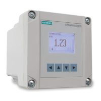
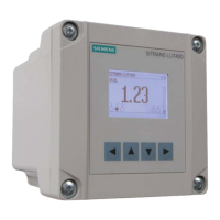
SITRANS LUT400
30 Operating Instructions, 07/2019, A5E33329501-AC
Groove for screwdriver (3 places)
For a more detailed dimension drawing, see SITRANS LUT400 Dimensions (Page 288).
4.2.4.2 Cable exposed and entering through the cable glands
6. After preparing for cable entry in steps 1 to 5 above, unscrew the glands and attach them
firmly to the enclosure.
7. Thread the cables through the glands. Ensure the power cable is kept separated from the
signal cables and then wire the cables to the terminal blocks.
8. Tighten the glands to form a good seal.
9. Replace enclosure lid and tighten screws.
Note
• When cable entry hole knock
-out tabs have been removed, the entry hole is 21.4 mm to
• M20 cable glands (20 mm in diameter), and 1/2" NPT conduit (21.3 mm in diameter) fit this
entry hole.
• Caution should be taken when selecting a
ppropriate seal for entry holes. Flat gasket is
recommended (instead of O
-ring). If alternate cable glands are used, it is the customer’s
responsibility to maintain IP65 rating of entry holes.
 Loading...