6-8
The relays have one set of voltage-free contacts (see note below) connected to one pair of
terminals via a header. The two terminals are configured for normally closed or normally
open by positioning a jumper on the header.
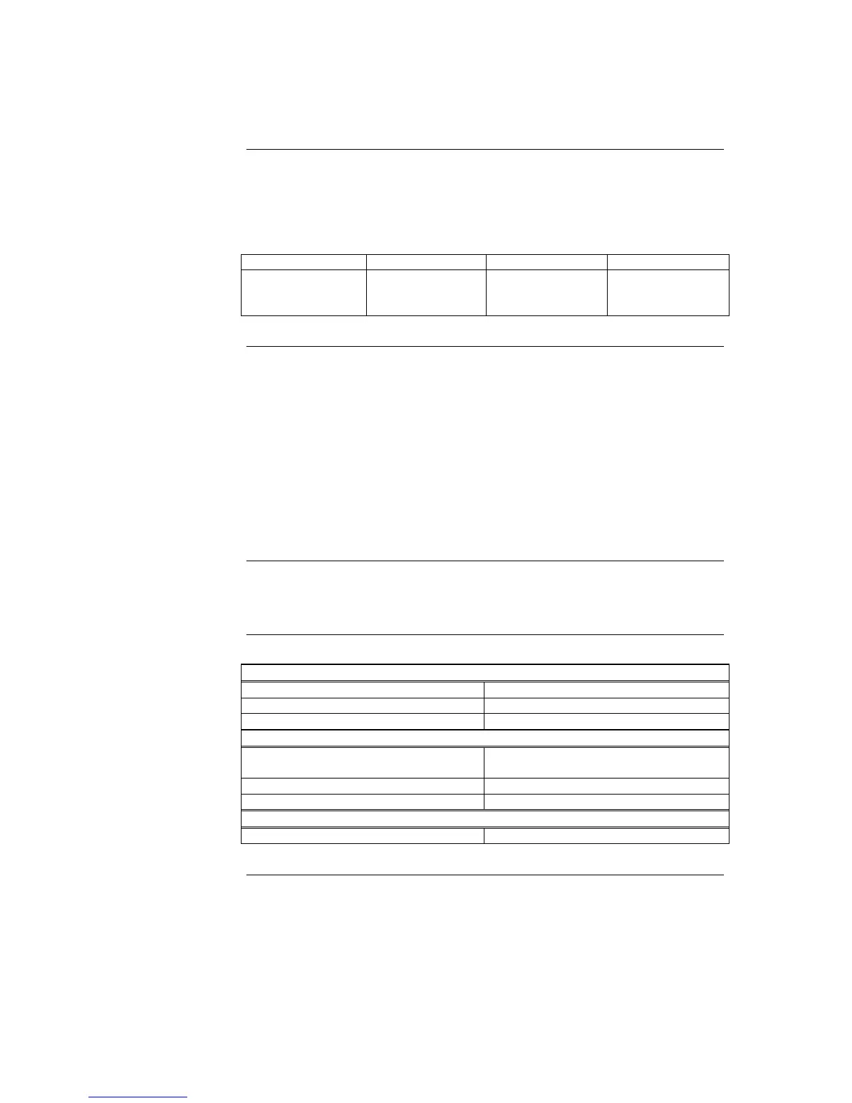
Table 6-3. Alarm Relay Card Jumper Positions
Relay Header Normally Closed Normally Open
Alarm
Isolate (Supervisory)
Fault (Trouble)
P1
P2
P3
1-2 (top)
1-2 (top)
1-2 (top)
2-3 (bottom)
2-3 (bottom)
2-3 (bottom)
• The common contact of each relay has a transient suppressor to earth, and must not be
used to switch voltages greater than its rating.
• The common contact is protected with a 3A fuse.
• For default configuration the relays are normally de-energised and energise on
Fault/Isolate/Alarm.
• The corresponding LED illuminates when the relay is energized.
• The relays may be configured under custom control to operate other than default.
If relay RL3 is configured for operation other than Fault (Trouble), jumper P3 on the SPS
must be shifted to positions 1-2 (top).
CARD
Input Voltage 20-32Vdc
Input Current 15mA @ 24V, quiescent
(nominal) 37mA @ 24V, all relays on
RELAYS
Form Voltage-free changeover, suppresses to
earth
Voltage 30Vac, 32Vdc
Current 2A, resistive load
FUSE
F1, F2, F3 5 x 15mm, Glass Cartridge, 3A (208-163)
The Alarm Relay Card, Continued
Configuration
Notes
Warning
Specification