EasyManuals Logo

Simplex 4100U Installation & Maintenance

Simplex 4100U
180 pages
To Next Page IconTo Next Page
To Previous Page IconTo Previous Page
Page #96 background imageLoading...
Page #96 background image
5-16
The Table below lists the 4100U master motherboard connections for the wired media
card.
Table 5-5. 566-227 CPU Motherboard Wired Media Connections
Motherboard Port for Media
Card Connected to P5
Wired Media Card Connection
(Left Port)
TB1-4 0 V
TB1-5 Earth ground
TB1-6 INV (-)
TB1-7 None
TB1-8 NONINV (+)
Motherboard Port for Media
Card Connected to P6
Wired Media Card Connection
(Right Port)
TB3-1 NONINV (+)
TB3-2 Reserved
TB3-3 INV (-)
TB3-4 Earth ground
TB3-5 0 V
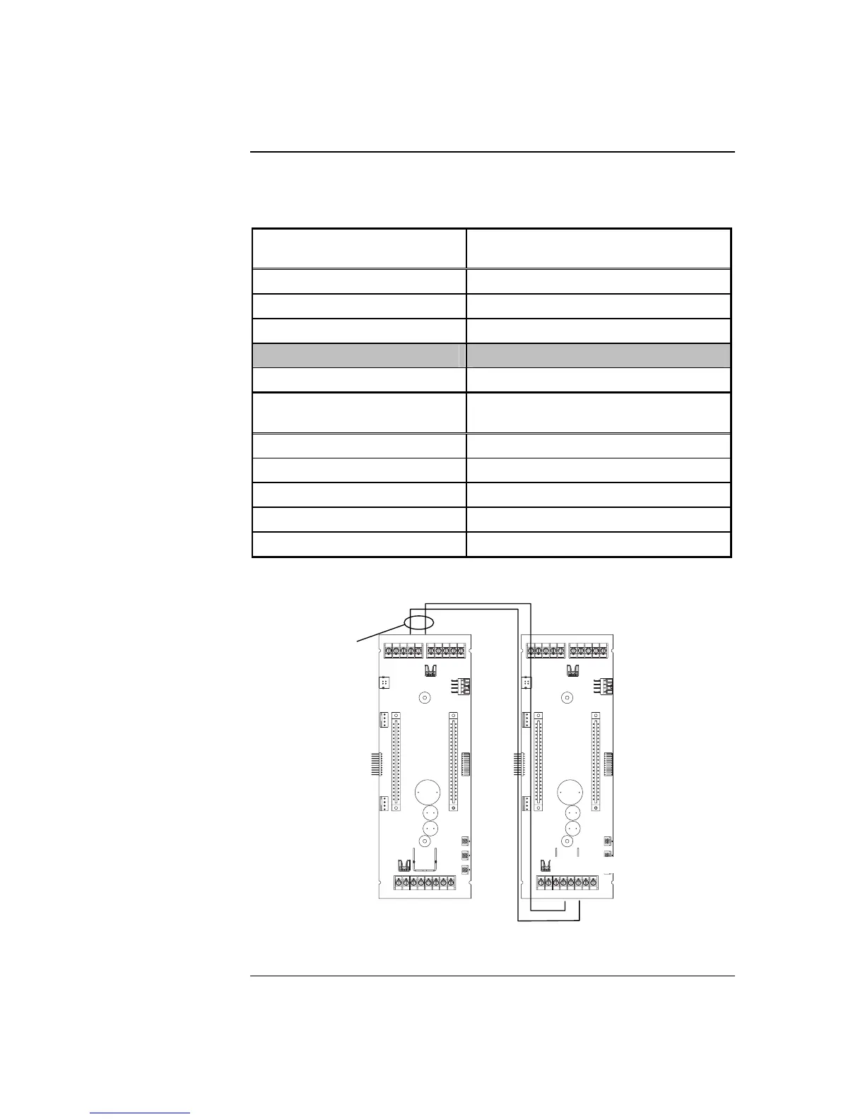
Figure 5-11, below, shows how two CPU motherboards with wired media network cards
connect to each other in the 4100U.
Figure 5-11. Wired Media Interconnections Between 4100U Motherboards
Continued on next page
Step 4. Wiring Network Cards, Continued
Wiring with the
Wired Media Card
(continued)
18 AWG
1 TB3 10
XMIT RCV
8 TB1 1
XMIT RCV

Table of Contents

Other manuals for Simplex 4100U

Questions and Answers:

Question and Answer IconNeed help?

Do you have a question about the Simplex 4100U and is the answer not in the manual?

Simplex 4100U Specifications

General IconGeneral
Control Panel TypeAddressable Fire Alarm Control Panel
DisplayLCD
Power Supply120/240 VAC, 50/60 Hz
Max Signaling Line Circuits (SLC)2
Operating Temperature0°C to 49°C (32°F to 120°F)
Humidity Range10% to 93% non-condensing
Network CapabilityYes
Communication ProtocolRS-232, RS-485
Battery Backup24 VDC
NAC Outputs4
Signaling Line Circuits (SLCs)2
Power Supply Current3.0 A
Max Notification Appliance Circuits (NAC)4
Max Releasing Circuits4
Max Relay Circuits4
Communication PortsRS-232, RS-485

Related product manuals