3-36
The RIC II motherboard is installed into a remote transponder cabinet. Review the
following guidelines before mounting RIC II motherboard.
• If a power supply is installed in the bay, it must be installed on the far right of
the bay and any relay modules must be installed in the slots immediately to its
left.
• Relay cards must be installed in the rightmost possible slots. This is necessary to
allow for the proper routing of non-power limited wiring (typically 120 VAC
wiring), which could be connected to a relay module.
Use the following directions and Figure 3-5 to install a RIC II motherboard into a
transponder cabinet.
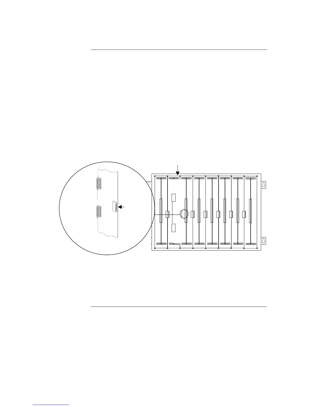
1. The RIC II motherboard must be installed in the leftmost slot. Orient the
motherboard with the connector labeled J1 on the right.
2. Secure the motherboard to the chassis with four torx screws.
Figure 3-5. Installing the RIC II Motherboard into a 4100 Expansion Bay
3. If you are installing the RIC II in a transponder cabinet with additional bays, you
must connect a 733-525 Power and Communication Harness. Continue to the
next topic for instructions.
Continued on next page
Installing Modules into Cabinets (Non-4100U), Continued
Installing the RIC II
Motherboard
The RIC II motherboard must be installed in the
leftmost slot.
RIC II
J1