5-13
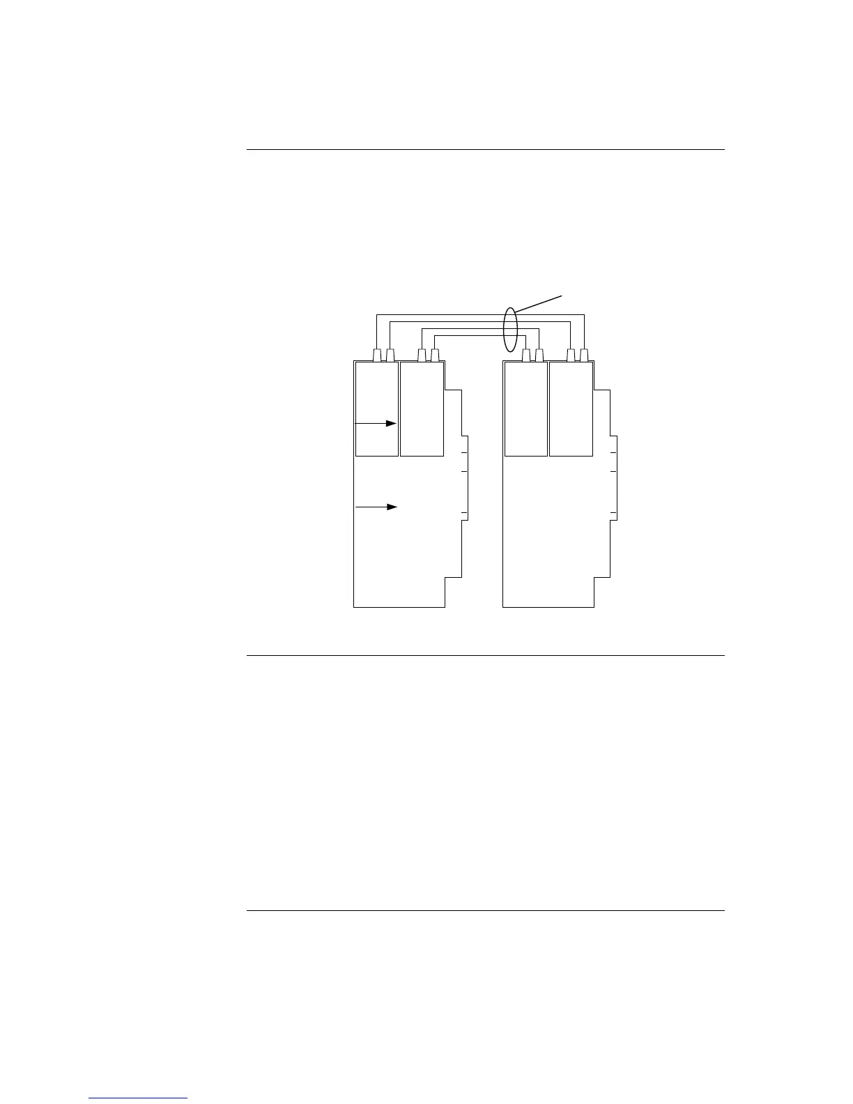
Connectors U1 (transmitter) and U2 (receiver) on the 4100-6057 Fiber-Optic Media Card
are used to connect 4100-6014 NICs across parts of a network.
Note: ST connectors with long strain relief boots are to be used with the fiber
optic cable.
Figure 6-10 shows how two network nodes are connected via fiber-optic cable.
U1 U2 U1 U2 U1 U2 U1 U2
Figure 5-9. Fiber Wiring
Dual Fiber Optic Cable Connections. The standard fiber optic connection between
network nodes uses two fiber optic cables, one for transmit, and the other for receive.
This connection allows for optimum communications distance.
The available communications distance is determined by the properties of the specific
fiber cable used. Distances can be determined using the information and examples shown
below in Table 6-3.
Single Fiber Optic Cable Connections. For applications where a single fiber cable is
available, or where use of a single cable is desired, using a model 4190-9010
Bi-Directional Coupler at each node combines the separate transmit and receive signals
into a single path (refer to the requirements list).
This connection allows use of a single fiber cable, but it does reduce communications
distance as indicated in the information and examples shown below in Table 6-4.
Continued on next page
Step 4. Wiring Network Cards, Continued
Fiber-Optic Wiring
Fiber Optic
Connection Types
FIBER MEDIA CARD
4100-6014
NETWOR