2-17
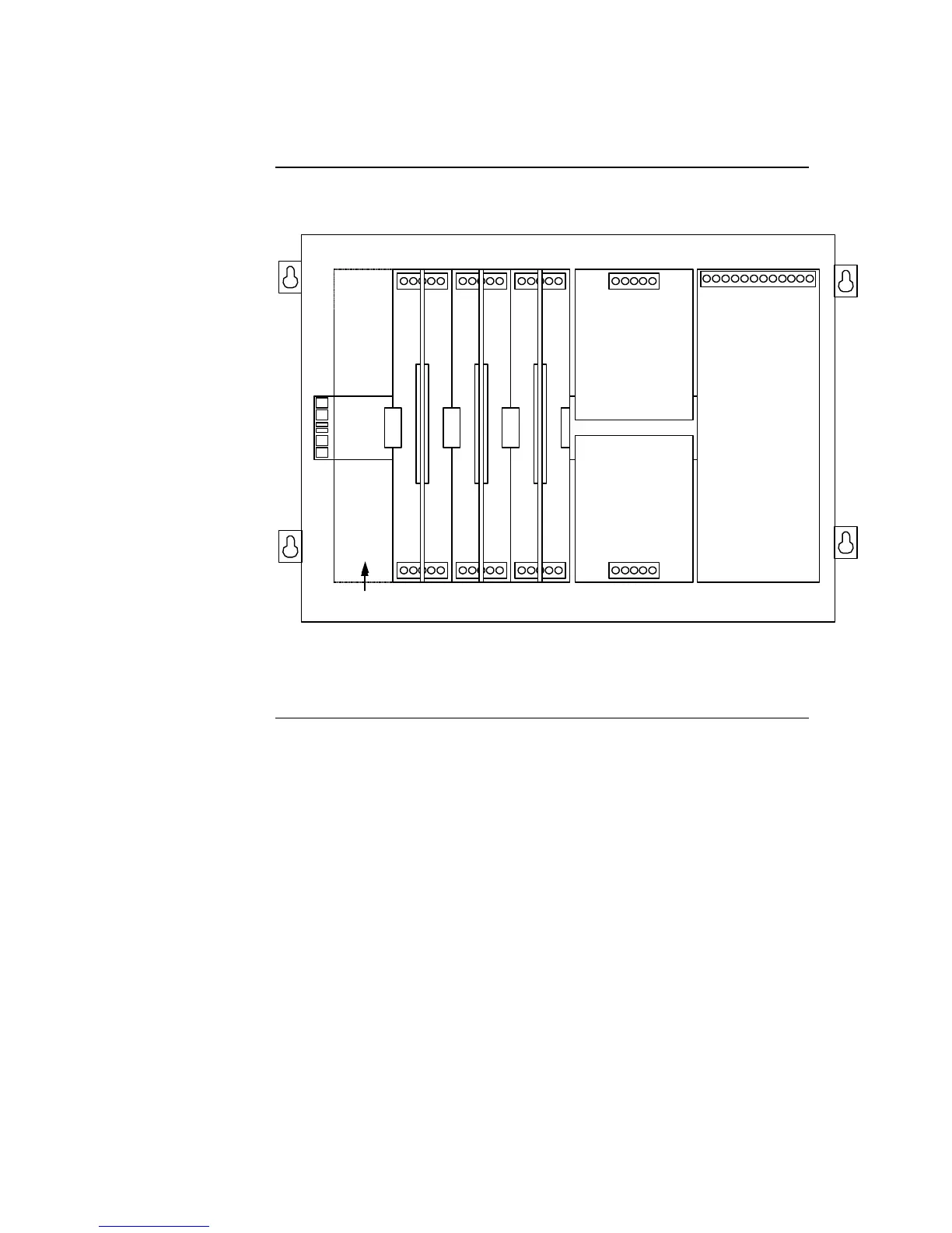
• As shown in the figure below, motherboards can be installed alongside
4”x 5” cards, if necessary.
No Boards
Allowed
in
This Slot
PDI
Expansion Power
Supply
(XPS)
I/O Wiring
I/O Wiring
I/O Wiring
4100 Option
4100 Option
4100 Option
Slot 1 Slot 2 Slot 3 Slot 4
Position
5
Position
6
Position
7 & 8
Block E Slots 7 + 8
Block F
This slot cannot contain a motherboard unless the pins
on P1 (or leftmost pin connector) are removed.
4" (102 mm) x 5" (127 mm)
Module
4" (102 mm) x 5" (127 mm)
Module
(Note. Australian SPS is 4 slots wide. XPS is not available in Australia.)
Figure 2-11. Mixed Module Placement
Continued on next page
Step 5. Installing Modules into Expansion Bays (4100U), Continued
Placement
Guidelines
(continued)