5-12
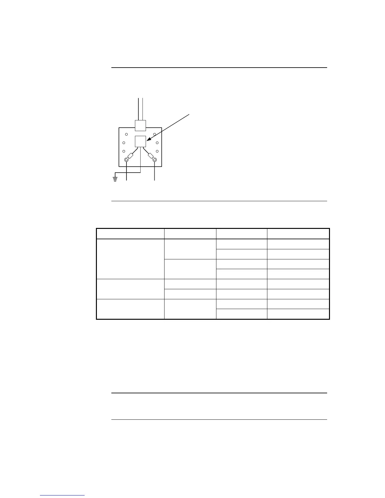
• 655-158 Transient Suppressor (ordered as part of 748-599) is required for each
modem-to-telephone line connection.
From Modem
8
5
Grn
Telephone Line
1
4
7
6
2
3
Figure 5-8. The Transient Suppressor
Maximum wiring distances are shown in the Table below and in Appendix J.
Table 5-2. Wiring Distances
Media Type Size Data Rate Max Distance
57.6 kbps 7,000 ft (2,134 m)
24 AWG
(0.2047 mm
2
)
9.6 kbps 12,000 ft (3,658 m)
57.6 kbps 10,000 ft (3,048 m)
Wired
18 AWG
(0.8231 mm
2
)
9.6 kbps 17,000 ft (5,182 m)
50/125 um 57.6 or 9.6 kbps 10,000 ft (3,048 m)
Optical Fiber
62.5/125 um 57.6 or 9.6 kbps 15,000 ft (4,572 m)
57.6 kbps 50 ft (15 m)
RS-232
18 AWG
(0.8231 mm
2
)
9.6 kbps 300 ft (91 m)
Notes:
• The characteristics for 0.75 mm
2
are shown in Appendix J.
• 18 AWG (0.8231 mm
2
) fire-rated twisted, shielded pair must not exceed 58
pF per foot and be less than or equal to 6.385 Ohms per 1,000 feet (305 m).
• 24 AWG (0.2047 mm
2
) twisted, unshielded telephone cable must not exceed
22 pF per foot and be less than or equal to 25.6 Ohms per 1,000 feet (305
m).
Refer to the 900-242 Field Wiring Specifications or 900-143 Fiber Tutorial for additional
NIC wiring information.
Continued on next page
Step 4. Wiring Network Cards, Continued
Wiring Distances
Related
Documentation
Transient Suppressor Assembly (655-158)
added to RJ-31x as shown. If connecting to a
terminal block, cut off one end of the cable.
Strip back the cable to connect the two center
wires, normally red and green, to the red and
green wires in the block.