EasyManuals Logo

Simplex 4100U Installation & Maintenance

Simplex 4100U
180 pages
To Next Page IconTo Next Page
To Previous Page IconTo Previous Page
Page #32 background imageLoading...
Page #32 background image
2-4
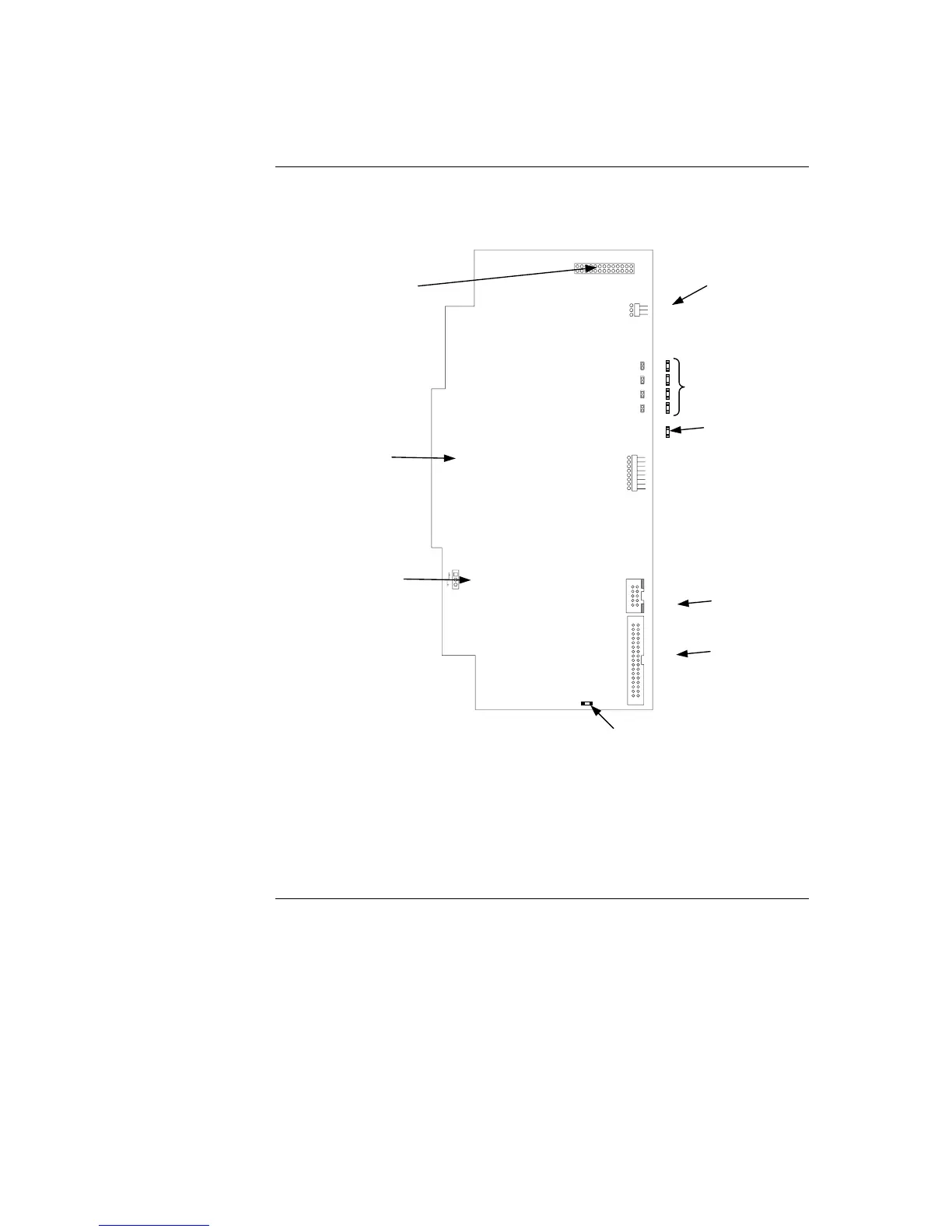
The master controller daughter card mounts onto the master motherboard. The master
controller daughter card contains a service port, a direct drive user interface connection,
and a port for a service modem.
MODEM
2
LED1 LED2 LED3
SERVICE PORT DISPLAY
CPU CARD
BD ASSY
566-149
BAT ON BAT OFF
Figure 2-2. Master Controller Daughter Card (566-149)
Continued on next page
Introduction to FACPs (4100U), Continued
Master Controller
Daughter Card
SERVICE MODEM
CONNECTOR (P4)
BATTERY BACKUP
ON/ OFF JUMPER (P3)
SERVICE PORT (P5)
DIRECT-DRIVE
DISPLAY PORT (P6)
CONNECTOR TO CPU
MOTHERBOARD (P9)
SERVICE PORT
COMM JUMPER (P1)
CPU BOOTLOADER LEDs
(LED1 – LED4)
TROUBLE LED (LD5)
TROUBLE LED (LED5):
OFF: No trouble.
FLASHING: CPU has power but the software is
failing to hit the watchdog
ON: The 5 V is outside the acceptable range
WARM START
SWITCH (SW1)

Table of Contents

Other manuals for Simplex 4100U

Questions and Answers:

Question and Answer IconNeed help?

Do you have a question about the Simplex 4100U and is the answer not in the manual?

Simplex 4100U Specifications

General IconGeneral
Control Panel TypeAddressable Fire Alarm Control Panel
DisplayLCD
Power Supply120/240 VAC, 50/60 Hz
Max Signaling Line Circuits (SLC)2
Operating Temperature0°C to 49°C (32°F to 120°F)
Humidity Range10% to 93% non-condensing
Network CapabilityYes
Communication ProtocolRS-232, RS-485
Battery Backup24 VDC
NAC Outputs4
Signaling Line Circuits (SLCs)2
Power Supply Current3.0 A
Max Notification Appliance Circuits (NAC)4
Max Releasing Circuits4
Max Relay Circuits4
Communication PortsRS-232, RS-485

Related product manuals