11-1
When a branch designs a system and orders a 4100U panel, a “Configuration Sheet” is
prepared. The factory builds the panel to the configuration sheet. This includes fitting,
connecting and configuring cards and modules.
The factory programs and tests the panel to the configured sheet.
The CPU Card and any 4100 style (legacy) cards that are fitted to motherboards are then
removed and packaged with the panel for shipping.
When the panel arrives on site the installers must unpack and check the panel, mount the
cabinet, refit any packaged cards, and check the configuration before applying power.
A registered electrician must connect the mains. The panel should then be powered up
and checked for correct operation.
With the mains turned off and the batteries disconnected, the field wiring is checked and
connected to the field terminals on the various cards.
The panel should then be powered up and re-programmed to accommodate all the
connected field devices. Faults in the field wiring, misaddressed detectors / devices,
mismatched detectors / devices will be displayed on the LCD. These should be cleared
one at a time and then the system (panel plus connected devices) should be
commissioned.
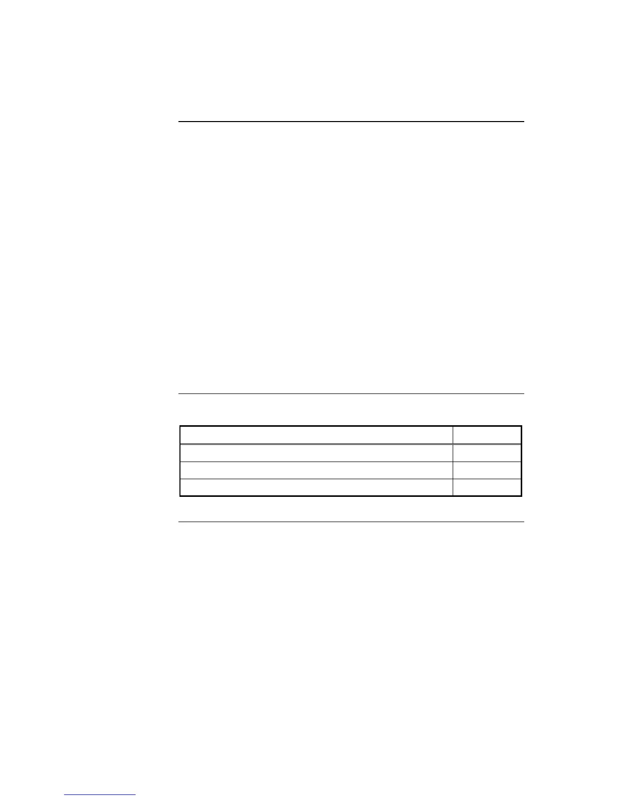
Refer to the page number listed in this table for information on a specific topic.
Topic See Page #
Installation Checklist
11-2
Alignment & Adjustment
11-3
Maintenance
11-5
Chapter 11
Installation Checklist, Commissioning & Maintenance
Introduction
In this Chapter